Apparatus for controlling engine

a technology for controlling apparatus and engine, which is applied in the direction of electric control, engine starters, machines/engines, etc., can solve the problems of affecting the smooth start of the engine, and affecting the operation of the engin

Inactive Publication Date: 2007-01-25
DENSO CORP
View PDF4 Cites 26 Cited by
  • Summary
  • Abstract
  • Description
  • Claims
  • Application Information

AI Technical Summary

Benefits of technology

[0015] It is thus an object of the present invention to provide a control apparatus, which is capable of properly controlling an engine having a variable-valve mechanism when the engine is automatically stopped.
[0016] It is another object of the present invention to provide a control apparatus, which is capable of properly controlling an engine having a variable-valve mechanism when the engine is automatically started.
[0017] It is a further object of the present invention to provide a control apparatus, which is capable of smoothly starting an engine having a variable-valve mechanism when the engine is automatically started.

Problems solved by technology

For this reason, a relatively large pumping loss is incurred.
In a typical engine, the execution of variable-valve control makes it unnecessary to install a throttle valve.
In this case, in the next automatic start control based on the saved valve operation characteristic, it is feared that a smooth start of the engine is obstructed.
Thus, there is a case in which, by execution of the variable-valve control, the intake airflow cannot be adjusted properly.
As a result, a torque shock is generated.
As a result, resonance occurs, temporarily increasing the amplitude of vibration and the magnitude of noise.
As a result, there appears a tendency to reduction of the battery voltage.
When the voltage of the battery decreases, the variable-valve mechanism does not operate in a stable manner in some cases.
When the voltage of the battery decreases, for example, it is quite within the bounds of possibility that the operation characteristic of the valve cannot be controlled to follow a target operation characteristic.
As a result, it is feared that the exhaust emissions deteriorate.

Method used


Image

  • Apparatus for controlling engine
  • Apparatus for controlling engine
  • Apparatus for controlling engine

Examples


first embodiment

[0080] First Embodiment

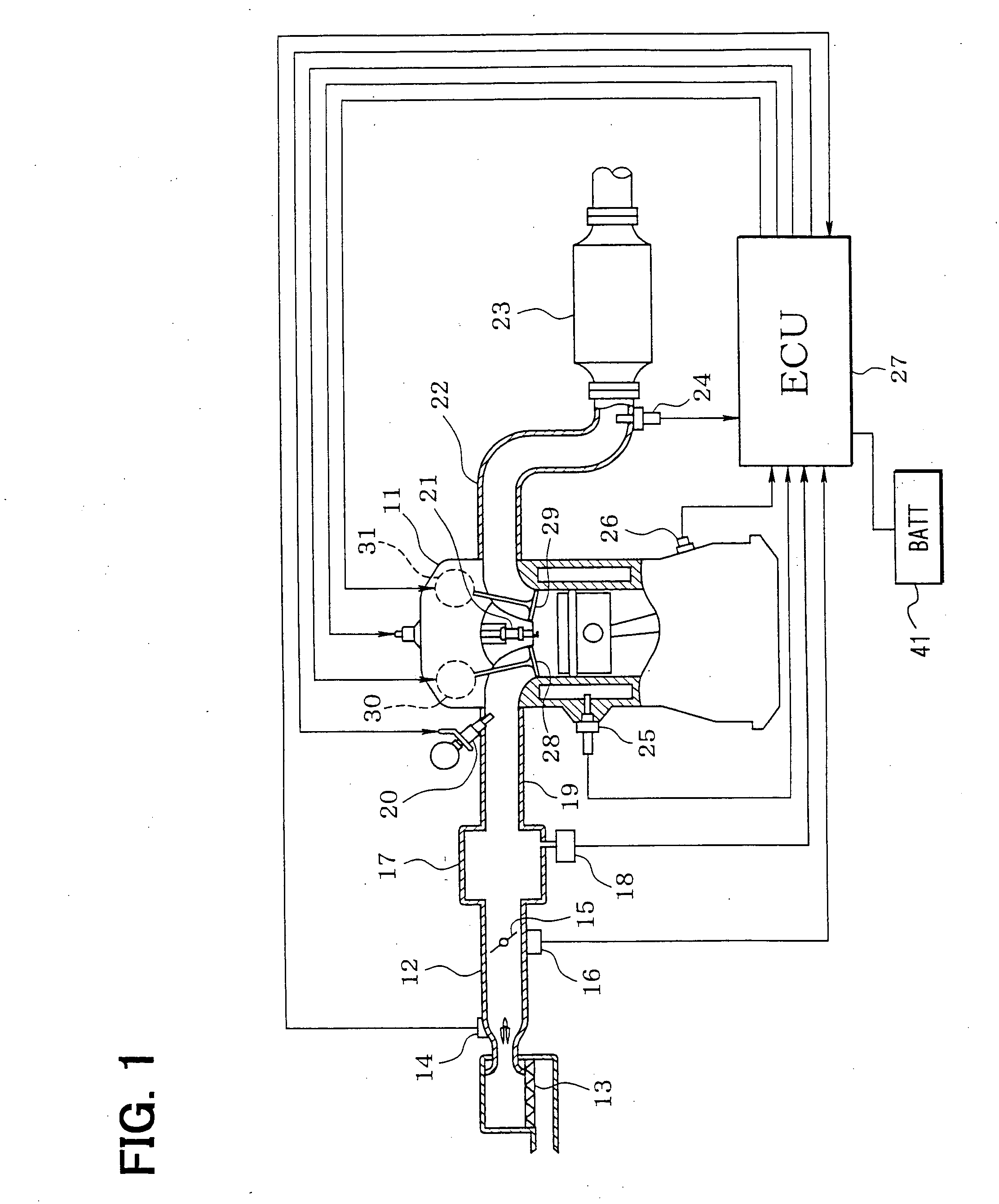
[0081] Some preferred embodiments of the present invention are explained by referring to diagrams as follows. First of all, a rough configuration of an entire engine control system is explained by referring to FIG. 1. An air cleaner 13 is provided at the upper end of the upstream side of an intake pipe 12 employed in an internal combustion engine 11. An airflow meter 14 for detecting an intake airflow is provided the downstream of the air cleaner 13. Downstream of the airflow meter 14, there are provided a throttle valve 15, the opening of which can be adjusted by typically a DC motor, and a throttle-opening sensor 16 for detecting an opening of the throttle valve 15.

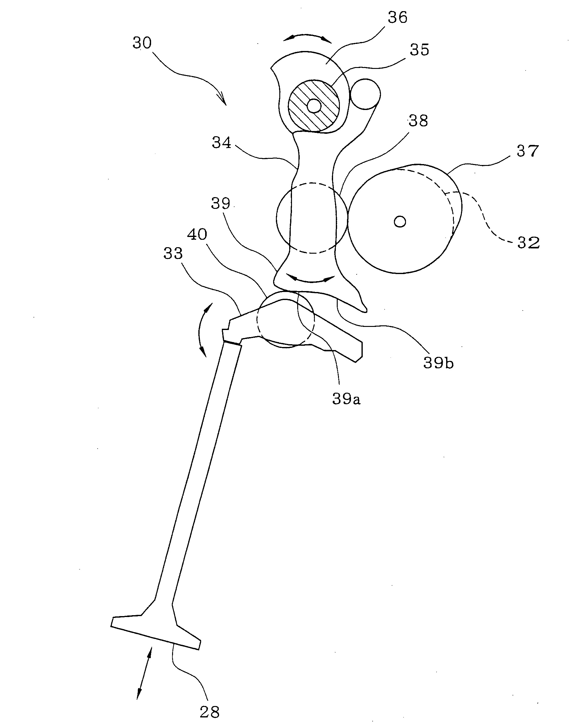
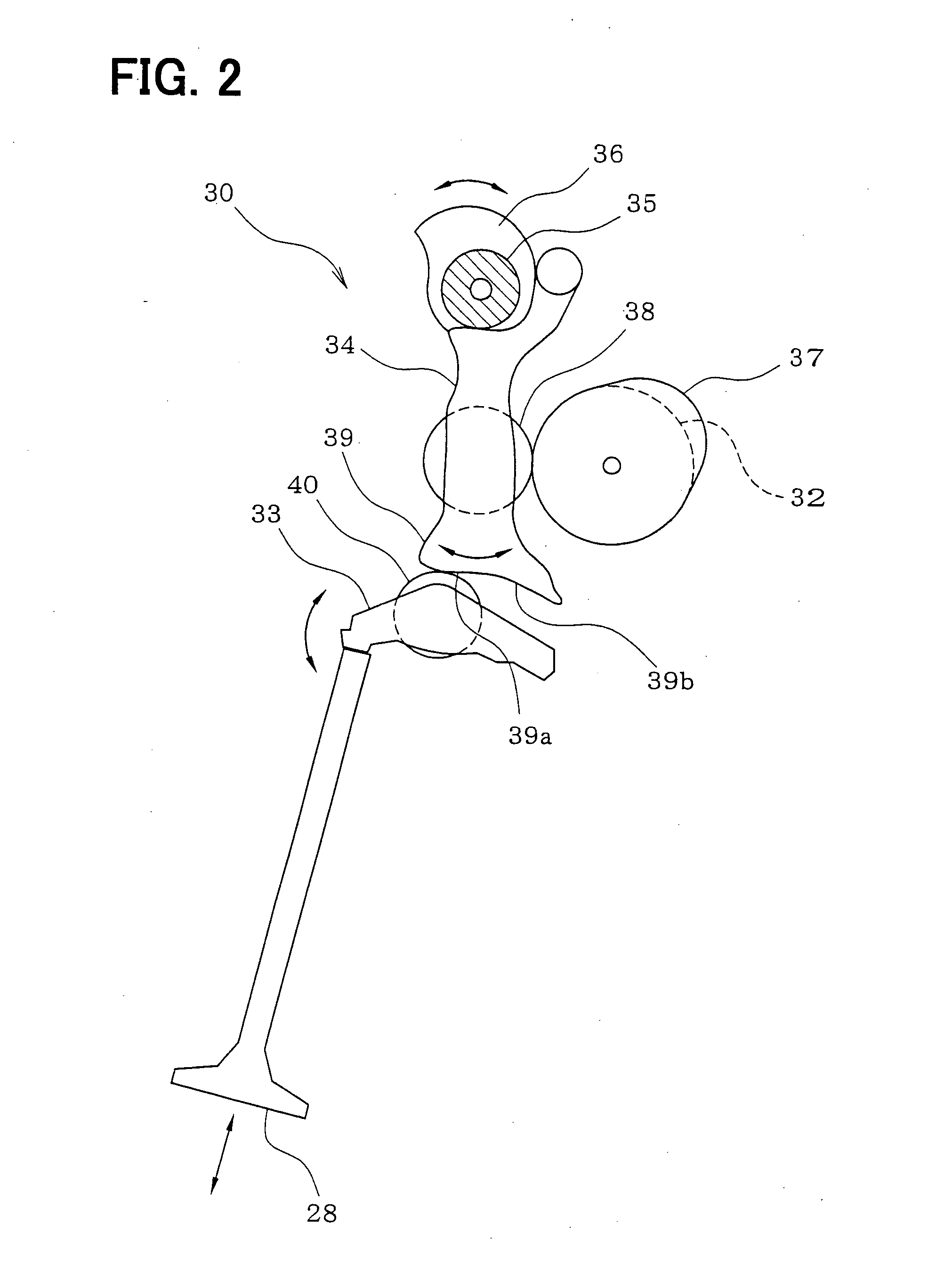
[0082] A surge tank 17 is further provided downstream of the throttle valve 15. On the surge tank 17, there is provided an intake-pipe-pressure sensor 18 for detecting a pressure of air in the intake pipe 12. In addition, on the surge tank 17, there is provided an intake manifold 19 for introduci...

second embodiment

[0159] Second Embodiment

[0160] Next, a second embodiment of the present invention is explained. The second embodiment has the same configuration as that shown in FIG. 1. In the case of the second embodiment, however, processing represented by a flowchart shown in FIG. 15 is carried out as a substitute for the first embodiment's processing represented by the flowchart shown in FIG. 8. The other control processing of the first embodiment is also carried out by the second embodiment.

[0161] An automatic-start control program stored in a ROM and represented by the flowchart shown in FIG. 15 is executed by the ECU 27 to automatically start the engine 11 when predetermined automatic-start conditions are satisfied in an automatic-stop state of the engine 11 with a timing shown in time charts of FIG. 17. Then, till the time lapsing since the completion of the automatic start of the engine 11 exceeds a variable-valve control prohibition time KCAST, the valve lift quantities of the intake val...

third embodiment

[0178] Third Embodiment

[0179] Next, a third embodiment of the present invention is explained. The third embodiment has the same configuration as that shown in FIG. 1. In the case of the third embodiment, however, processing represented by a flowchart shown in FIG. 18 is carried out as a substitute for the first embodiment's processing represented by the flowchart shown in FIG. 8. The other control processing of the first embodiment is also carried out by the third embodiment.

[0180] An automatic-start control program stored in a ROM and represented by the flowchart shown in FIG. 18 is executed by the ECU 27 to automatically start the engine 11 when predetermined automatic-start conditions are satisfied in an automatic-stop state of the engine 11. It is to be noted that, at that time, the variable-valve lift mechanisms 30 and 31 are each set at a position proper for a restart operation.

[0181] The ECU 27 executes the automatic-start control program represented by the flowchart shown ...


PUM


Abstract

An engine has variable-valve mechanisms. An engine control system has an engine control unit for executing automatic stop and start control. At an automatic-stop, the variable-valve mechanisms are controlled to obtain a valve operation characteristic suitable for a restart of the engine. When a catalyst is in an inactivated state, the variable-valve mechanisms are controlled to reduce the amount of residual gas leaking out from cylinders. At an automatic-start, the control of the variable-valve mechanism is prohibited and an intake air is adjusted by using a throttle valve. At an automatic-stop, the engine speed is abruptly reduced so that the engine speed passes through a resonant revolution speed area in a short period of time. When the voltage of a battery is low, the control of the variable-valve mechanism may be prohibited.

Description

CROSS REFERENCE TO RELATED APPLICATION [0001] This application is based on Japanese Patent Applications No. 2001-372259 filed on Dec. 6, 2001, No. 2001-381015 filed on Dec. 14, 2001, No. 2001-383898 filed on Dec. 18, 2001 and No. 2002-12924 filed on Jan. 22, 2002 the contents of which are incorporated herein by reference. BACKGROUND OF THE INVENTION [0002] 1. Field of the Invention [0003] The present invention relates to an apparatus for controlling an internal combustion engine, which is also referred to hereafter simply as an engine. More particularly, the present invention relates to an apparatus for controlling an engine having a variable-valve mechanism. [0004] 2. Related Art [0005] In the conventional engine, a throttle valve is provided on an intake pipe of the engine. The throttle valve adjusts the opening thereof in order to control an intake airflow. The driver depresses an accelerator pedal connected to the throttle valve by an electrical link mechanism so that the valve ...

Claims


Application Information

Patent Timeline
Patent Type & Authority Applications(United States)
IPC IPC(8): F02D17/02F01L1/34F02M17/30F02N99/00F02D13/02F02D41/04F02D41/06F02N11/08
CPCF01L1/053Y02T10/48F01L13/0021F01L2013/0068F01L2800/00F02D13/0211F02D41/042F02D41/062F02D41/1456F02D41/187F02D2041/001F02D2041/0092F02D2041/0095F02D2200/0404F02D2200/0406F02D2200/503F02D2200/602F02N11/0818F02N2200/0801F02N2200/102F02N2200/103Y02T10/18F01L1/185Y02T10/12Y02T10/40
Inventor KONDO, WAKICHI
Owner DENSO CORP
Why Eureka
Try Eureka