Thermal printer and thermal printer control method

a control method and printer technology, applied in printing and other directions, can solve the problems of thermal printer generally overheating excessively, affecting print quality, and accumulating heat,

Active Publication Date: 2007-01-25
SEIKO EPSON CORP
View PDF4 Cites 8 Cited by
  • Summary
  • Abstract
  • Description
  • Claims
  • Application Information

AI Technical Summary

Benefits of technology

[0023] This aspect of the invention enables predicting the speed change. As a result, setting the hysteresis coefficient applied to the thermal print head when the prin

Problems solved by technology

For example, if the energization of the print head used to print each dot is the same used to print the previous line (one dot before), each energized heating element forming the dot will not cool sufficiently because the supplied electrical energy accumulates heat, and the temperature of the heating element forming the dot rises and d

Method used


Image

  • Thermal printer and thermal printer control method
  • Thermal printer and thermal printer control method
  • Thermal printer and thermal printer control method

Examples


Embodiment Construction

[0036] Print Speed Variation State

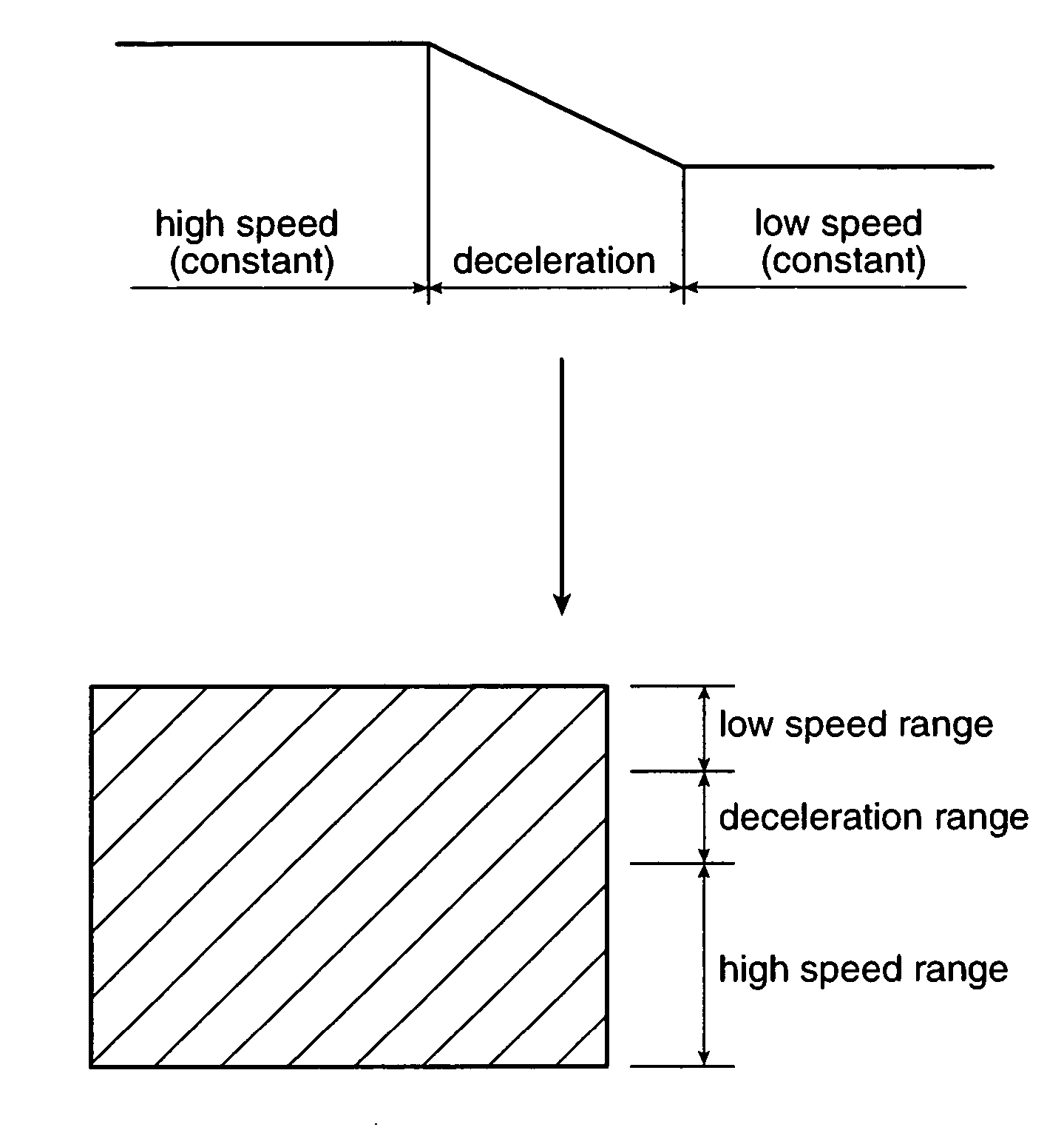
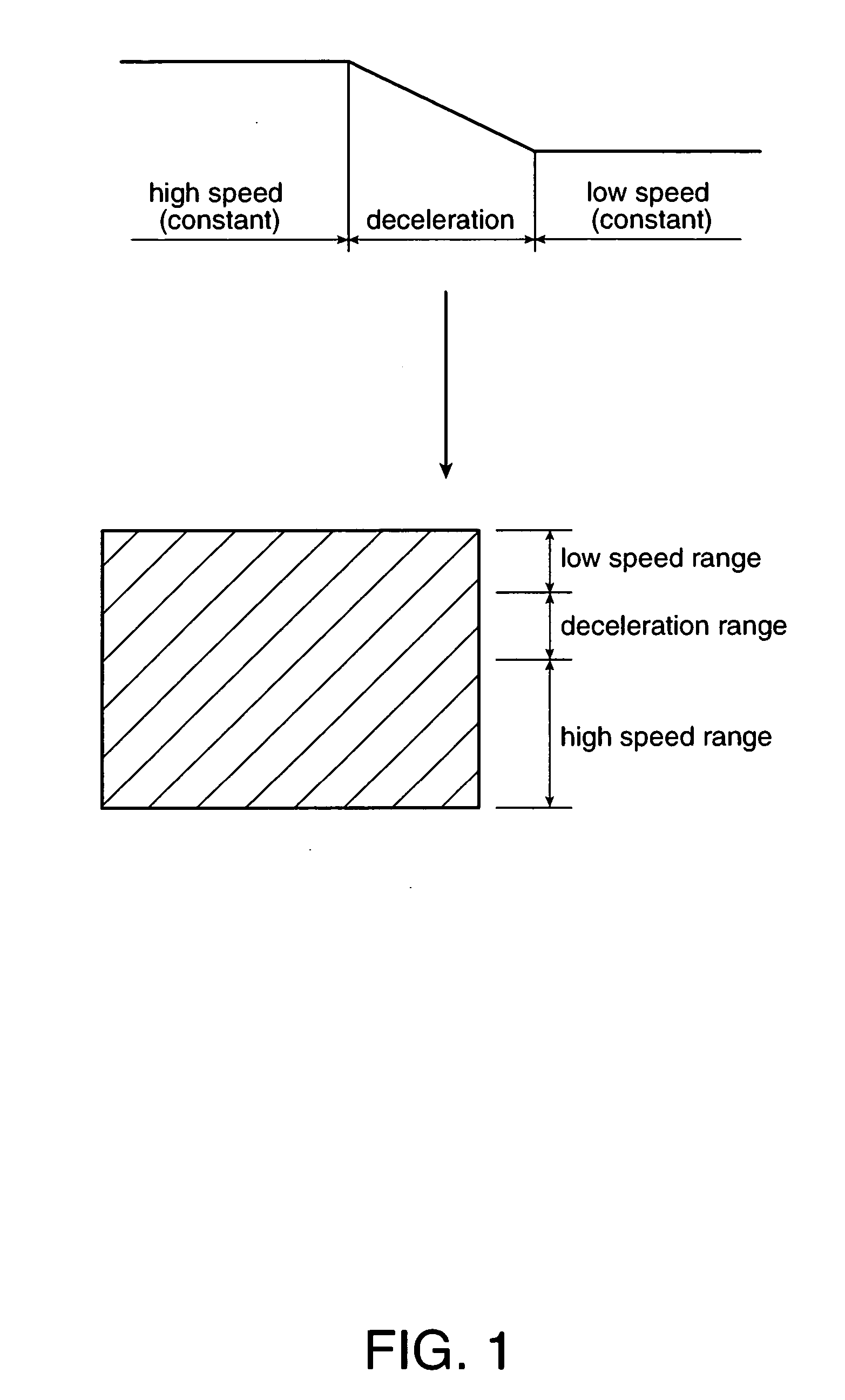
[0037] The thermal printer and control method of the present invention assures good print quality by monitoring the print speed variation state particularly during print speed deceleration. The print speed variation state as used herein is the state in which the print speed V (see FIG. 3) increases or decreases continuously for a predetermined period of time. As described above, the print duty often differs greatly when printing text and when printing a logo or other graphic, and the print speed V decreases continuously over a predetermined period of time during the transition from text printing to logo printing (such as during deceleration period 11 in FIG. 3). A drop in print quality is particularly pronounced when the rate of the decrease in the print speed V (the rate of deceleration) is high. More specifically, the drop in print quality increases as the drop in print speed V increases and the deceleration time decreases. In addition to the rat...


PUM


Abstract

High print quality from a thermal printer is maintained while the print speed is decreasing without producing white streaks or uneven print density by controlling the hysteresis coefficient of the thermal print head 35 based on the energizing history of the thermal print head 35 and print speed control factors used for determining print speed,which is the speed at which the paper is advanced while printing. The thermal printer, comprises a hysteresis coefficient setting unit 2 for setting a hysteresis coefficient for the print head based on the energizing history of the thermal print head 35; an energizing time calculation unit 3 for calculating the energizing time during which drive signals are to be applied to the thermal print head 35 for printing based upon the hysteresis coefficient set by the hysteresis coefficient setting unit; a printing control device 4 for generating the drive signals to be applied to the print head in response to the energizing time calculated by the energizing time calculation unit 3; a print speed determination unit 5 for determining the change in the print speed and when the print speed is decreasing; and a coefficient changing unit 6 for changing the hysteresis coefficient when a change in print speed occurs causing the print speed to decrease. Preferably the coefficient changing unit changes the hysteresis coefficient to a value greater than the hysteresis coefficient value used immediately before deceleration.

Description

BACKGROUND OF THE INVENTION [0001] 1. Field of technology [0002] The present invention relates to a thermal printer and to a control method for the thermal printer. [0003] 2. Description of Related Art [0004] Thermal printers hold the thermal paper between the thermal print head and a platen roller and advance the paper by rotating the platen roller. The thermal print head has heating elements (dots) arrayed in a line (one dot line) across the width of the paper, and applies current to selected or all of the heating elements in this dot line to produce heat and cause the thermal paper to change color. The thermal printer prints “dots” by energizing the thermal print head while advancing the thermal paper. Torque for rotating the platen roller is transferred from a rotational drive source such as a stepping motor through a transfer mechanism (a gear train) to the platen roller. [0005] The printing speed of a thermal printer is determined by various parameters, including the energizin...

Claims


Application Information

Patent Timeline
IPC IPC(8): B41J2/00
CPCB41J2/355
Inventor KOYABU, AKIRANAKAJIMA, SATOSHITAKIGUCHI, YUJI
Owner SEIKO EPSON CORP
Why Eureka
Try Eureka