Optical tomography apparatus

a tomography apparatus and optical technology, applied in the field of optical tomography apparatus, can solve the problems of limiting the measurement depth of the oct apparatus, presently difficult to obtain definitive diagnoses during examination with an endoscope, and the possibility of metastasis, so as to improve the transmissivity of light beams, increase the options of light sources, and improve the effect of optical tomography

Active Publication Date: 2007-01-25
FUJIFILM HLDG CORP +1
View PDF12 Cites 210 Cited by
  • Summary
  • Abstract
  • Description
  • Claims
  • Application Information

AI Technical Summary

Benefits of technology

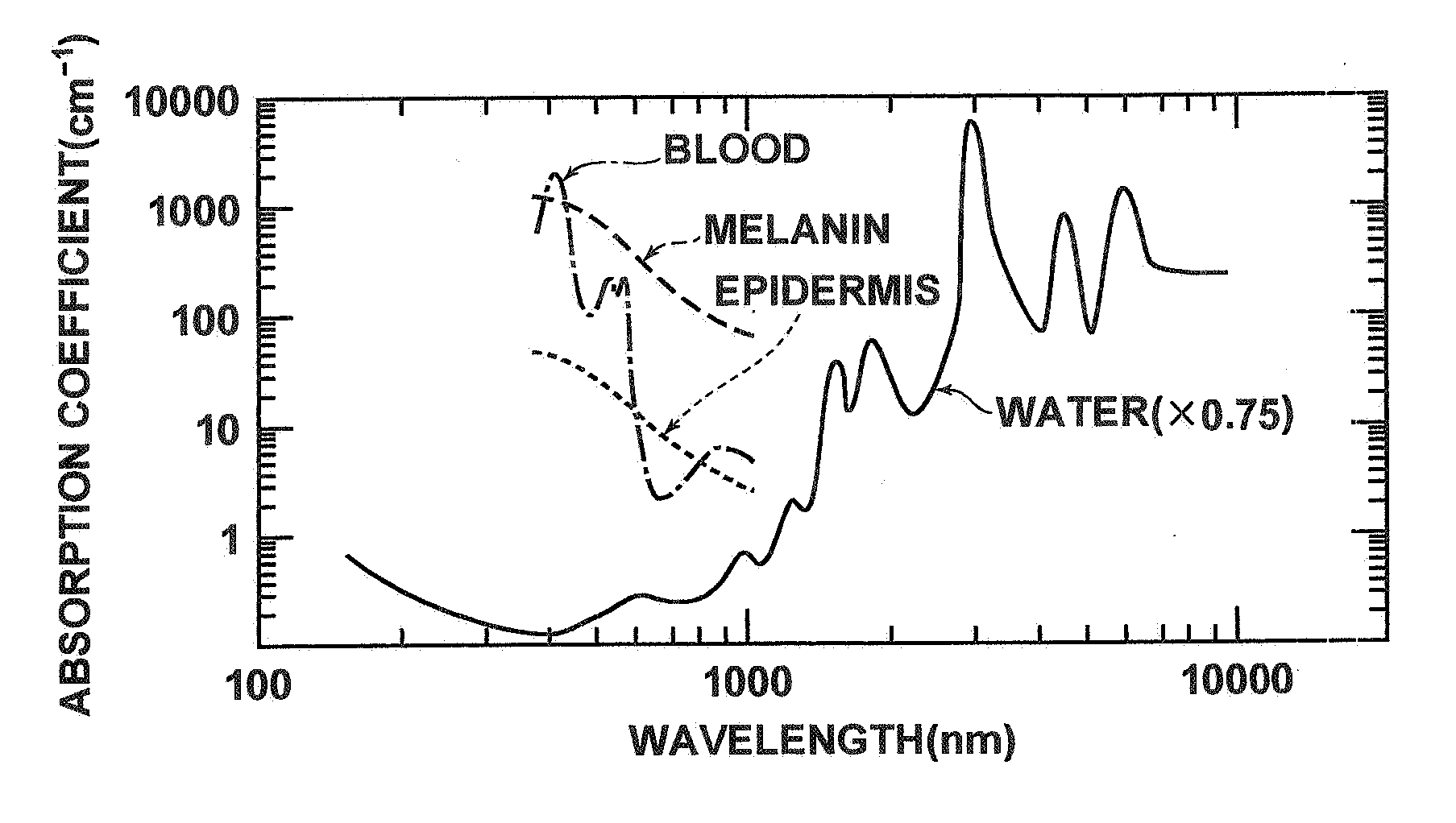
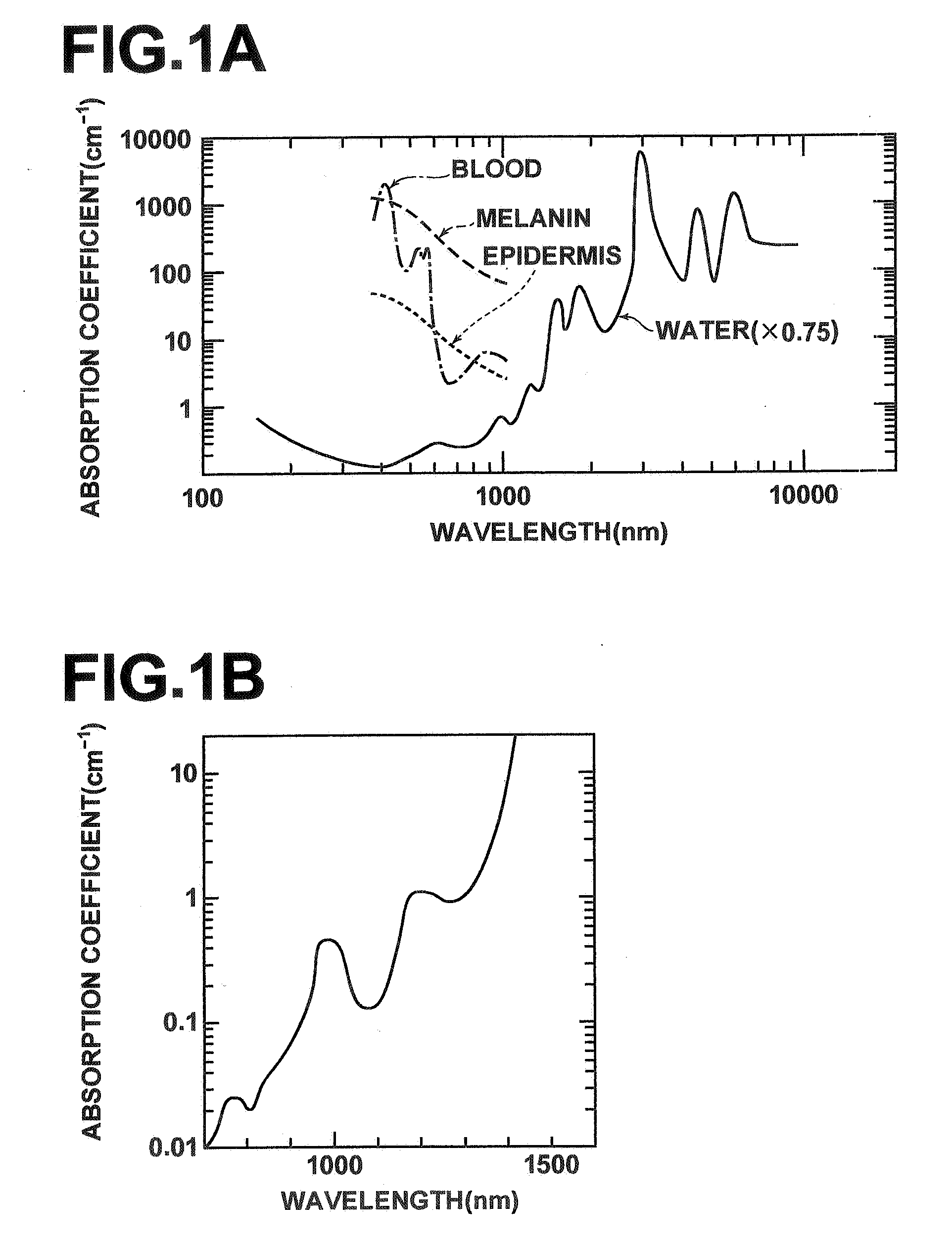
[0029] The present invention has been developed in view of the aforementioned problems. It is an object of the present invention to clarify the presence of optimal wavelength properties for obtaining high resolution while taking into consideration the light absorption properties, the scattering properties, and the dispersion properties of living organisms. It is another object of the present invention to realize an optical tomography apparatus that employs low coherence light or coherent light, of which the frequency is temporary varied, having the optimal wavelength properties to obtain high resolution optical tomographic images having high image quality.

Problems solved by technology

However, it has been found recently that scattering properties also limit measurement depths in OCT apparatuses.
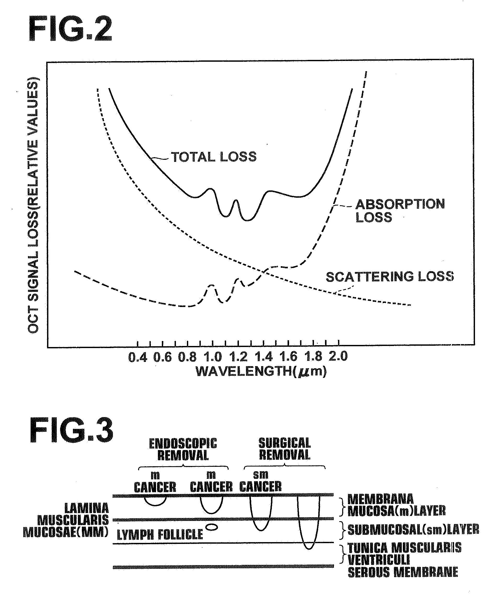
For this reason, it is presently difficult to obtain definitive diagnoses during examination with an endoscope.
Blood vessels and lymph systems are present in the submucosal layer, and there is a possibility of metastasis in the case of sm cancers.
However, the resolution of ultrasound imaging is only about 100 μm in the axial direction, which is insufficient to visualize the MM layer.
That is, it is not generally possible to obtain resolution less than the coherence length of the light source.
As a result, side bands appear in the autocorrelation waveform, pseudo signals are generated, and the quality of the optical tomographic image deteriorates.

Method used


Image

  • Optical tomography apparatus
  • Optical tomography apparatus
  • Optical tomography apparatus

Examples


first embodiment

[0106] Hereinafter, an optical tomography apparatus 200 according to the present invention will be described with reference to FIG. 9. FIG. 9 is a schematic diagram that illustrates the construction of the optical tomography apparatus 200.

[0107] The optical tomography apparatus 200 illustrated in FIG. 9 obtains tomographic images of measurement targets by the aforementioned TD-OCT measurement technique. The optical tomography apparatus 200 comprises: a light source unit 210, constituted by a light source 10 that emits a laser light beam La and a condensing lens 11; an optical fiber FB1; a light dividing means 2, for dividing the laser light beam La, which is emitted from the light source unit 210 and propagates through the optical fiber FB1; a light dividing means 3, for dividing the laser beam La, which has passed through the light dividing means 2, into a measuring light beam L1 and a reference light beam L2; an optical fiber FB3; an optical path length adjusting means 220, for ad...

third embodiment

[0157] Hereinafter, an optical tomography apparatus 600 according to the present invention will be described with reference to FIG. 21. FIG. 21 is a schematic diagram that illustrates the construction of the optical tomography apparatus 600.

[0158] The optical tomography apparatus 600 illustrated in FIG. 21 obtains tomographic images of measurement targets by the aforementioned SS-OCT measurement technique. The optical tomography apparatus 600 comprises: a light source unit 610, for emitting a laser light beam Ls; a light dividing means 63, for dividing the laser beam Ls into a measuring light beam Ls1 and a reference light beam Ls2; an optical path length adjusting means 520, for adjusting the optical path length of the reference light beam Ls2; an optical probe 630 that irradiates the measuring light beam Ls1 onto a measurement target Sb; a multiplexing means 64, for multiplexing a reflected light beam Ls3, which is the measuring light beam Ls1 reflected from the measurement target...


PUM


Abstract

Low coherence light having a central wavelength λc of 1.1 μm and a full width at half maximum spectrum Δλ of 90 nm is emitted. The low coherence light has wavelength properties suited for the light absorbing properties, the diffusion properties, and the dispersion properties of living tissue. A light dividing means divides the low coherence light into a measuring light beam, which is irradiated onto a measurement target via an optical probe, and a reference light beam that propagates toward an optical path length adjusting means. A multiplexing means multiplexes a reflected light beam, which is the measuring light beam reflected at a predetermined depth of the measurement target, and the reference light beam, to form coherent light. A coherent light detecting means detects the optical intensity of the multiplexed coherent light. An image obtaining means performs image processes, and displays an optical tomographic image on a display apparatus.

Description

BACKGROUND OF THE INVENTION [0001] 1. Field of the Invention [0002] The present invention relates to an optical tomography apparatus that irradiates a low coherence measuring light beam onto a measurement target to obtain tomographic images of the measurement target. Particularly, the present invention relates to an optical tomography apparatus that obtains images of the surface and the fine structures within the measurement target, based on a reflected light beam, which is the measuring light beam reflected by the measurement target. [0003] 2. Description of the Related Art [0004] As conventional methods for obtaining tomographic images of measurement targets, such as living tissue, methods that obtain optical tomographic images by OCT (Optical Coherence Tomography) measurement have been proposed. As an example of an OCT measurement method, the TD-OCT (Time Domain Optical Coherence Tomography) measurement has been proposed (refer to Japanese Unexamined Patent Publication Nos. 6(199...

Claims


Application Information

Patent Timeline
Patent Type & Authority Applications(United States)
IPC IPC(8): G01B9/02G01B11/02
CPCA61B5/0066A61B5/0071A61B5/0073A61B5/0084A61B5/0086G01B9/02014G01N21/4795G01B9/02004G01B9/02003G01B9/02044G01B9/02091G01J3/10
Inventor TOIDA, MASAHIROMORISHIMA, YOSHIKATSUTSUJITA, KAZUHIROFUJITA, HIROSHI
Owner FUJIFILM HLDG CORP
Why Eureka
Try Eureka