Surveying systems and methods

a surveillance system and detection system technology, applied in the field of surveillance, can solve the problems of prior art not addressing the problem of selecting a specific target, risk of total station locking on the wrong target, further compounding, etc., to save time and also security, and extend the range of communication.

Active Publication Date: 2007-01-25
TRIMBLE A B A CORP OF SWEDEN
View PDF8 Cites 84 Cited by
  • Summary
  • Abstract
  • Description
  • Claims
  • Application Information

AI Technical Summary

Benefits of technology

[0022] 6. facilitating selection of one target among several, when the separation of the targets is large enough to exclude unwanted targets,
[0052] By providing wireless data communication in each unit the possibility is present to relay data between several units such as to extend the range of the communication. This also provides the possibility of gathering all data at a common means for storing the data, such that there will be no need in downloading data from each unit separately, thus saving time and also security in that the data will be available at the common data storage and also in the individual total stations or the control units at the targets.

Problems solved by technology

This means there is a risk of a total station locking on the wrong target.
The prior art does not address the problem of selecting a specific target among several possible targets, when the targets appear to be closely located as viewed from the total station.
A further problem is encountered when several targets and several total stations are located on the same general site; the problem of unique identification of all elements in the survey for proper linking of target with total station is further compounded when there are different users in the same general site.

Method used


Image

  • Surveying systems and methods
  • Surveying systems and methods
  • Surveying systems and methods

Examples


Embodiment Construction

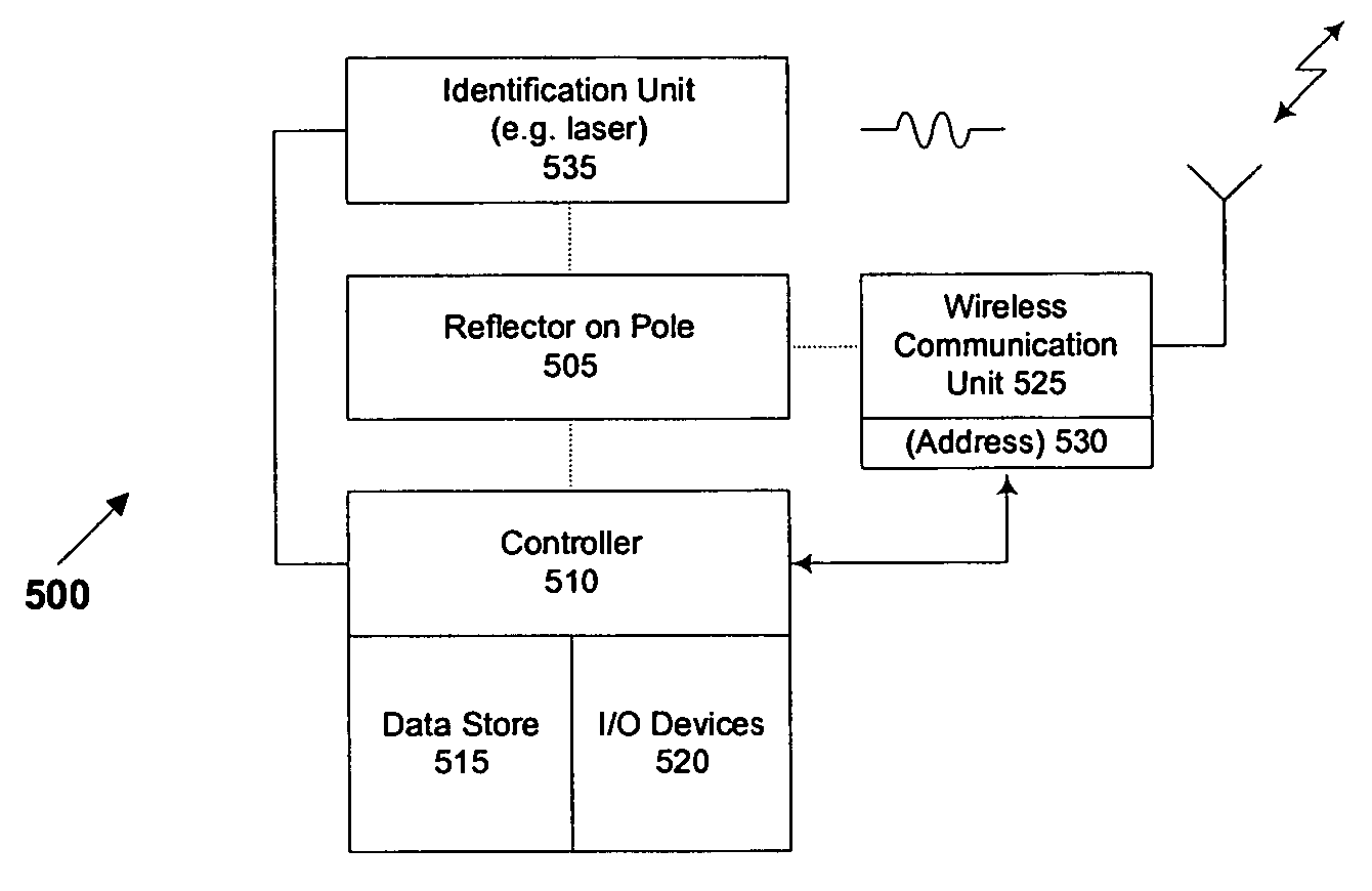
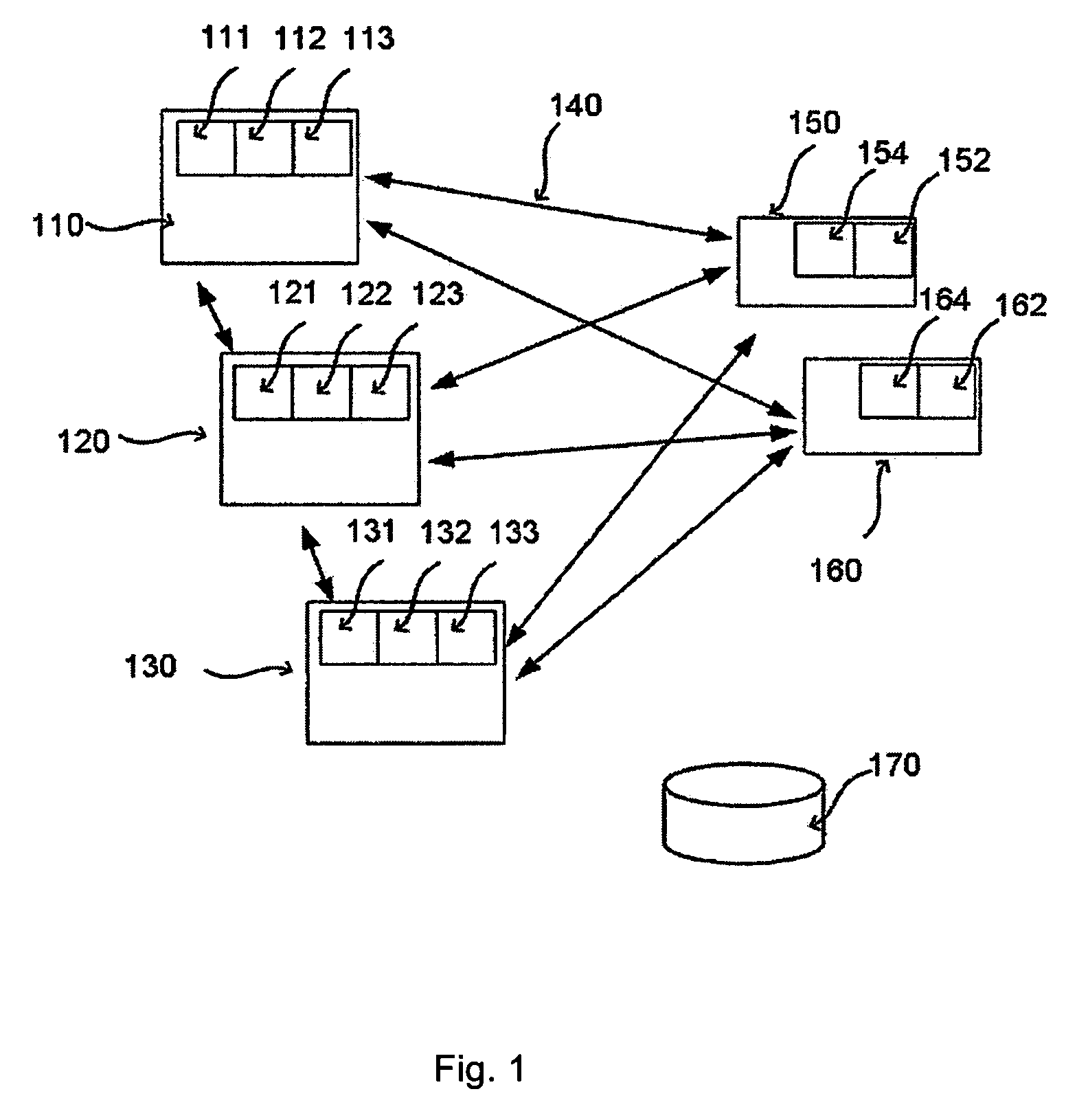
[0063] In a preferred embodiment of the invention, several total stations and targets interact as is shown in the schematic drawing in FIG. 1. Three total stations 110, 120, 130 are shown, each having arrangements 111, 121, 131 for sending out measuring beams for distance and alignment measurements, and beams, and sensor arrangements 112, 122, 132 for receiving the reflected or the transmitted beams from a target.

[0064] The sensor for receiving the alignment beam may be adapted to receive the beam from an identification unit at the target, or a separate sensor may be used for detection of this identification. Optical alignment means (telescope) may be arranged in order to align the total station(s) with any known point (not shown). Also provided are units for two-way wireless data communication, 113, 123, and 133, respectively.

[0065] The two-way wireless data communication may be of the cellular type, e.g. AMPS, PCS (Personal Communication Service) CDPD (Cellular Digital Packet Da...


PUM


Abstract

The invention relates to a surveying system, comprising at least one total station unit (210,220), and at least one target (201,203), said targets having wireless communication means, each unit provided with a unique wireless communication address for wireless communication, the wireless communication to be used to activate a selected total station (210,220) to identify and measure the location of a chosen target (201,203) in relation to a relative reference system, each target having identification means to be used by the total station for identification of the chosen target, each total station having identifying means used for identification of the chosen target to be measured. The invention also relates to a target and a method for surveying using the total stations and the targets according to the system.

Description

CROSS REFERENCE TO RELATED APPLICATIONS [0001] This is a continuation-in-part of co-pending U.S. application Ser. No. 11 / 159,431 filed 20 Jun. 2005, the content of which is incorporated herein by this reference, which in turn is a continuation-in-part of co-pending International Application PCT / SE2003 / 002028, with an international filing date of 19 Dec. 2003 and designating the United States of America, the content of which is incorporated herein by this reference. Priority benefit under 35 USC 119 is claimed of patent application number 0203830-5 filed in Sweden on 20 Dec. 2002, the content of which is incorporated herein by this reference.FIELD OF THE INVENTION [0002] The present invention generally relates to surveying and more specifically to a surveying system including several surveying units for surveying and equipment such as targets, radio receivers and methods and means for co-operation between such units. BACKGROUND OF THE INVENTION [0003] The art of surveying involves th...

Claims


Application Information

Patent Timeline
Patent Type & Authority Applications(United States)
IPC IPC(8): H04B10/00G01B11/14G01C1/00G01C15/00G01S5/00G01S13/87G01S17/74G01S19/49G01S19/51
CPCG01C15/00G01S17/74G01S13/878G01S5/0018
Inventor GATSIOS, GEORGIOSHOGLUND, ROGERHAMILTON, JEFFERY ALLEN
Owner TRIMBLE A B A CORP OF SWEDEN
Why Eureka
Try Eureka