Solid chemical hydride dispenser for generating hydrogen gas
a dispenser and solid chemical technology, applied in the direction of molybdeum compounds, synthetic resin layered products, weaving, etc., can solve the problems of significant decrease in the efficiency of the device, substantial amount of unreacted borohydride remaining in the spent generator, and the use of hydrogen generators
- Summary
- Abstract
- Description
- Claims
- Application Information
AI Technical Summary
Problems solved by technology
Method used
Image
Examples
second embodiment
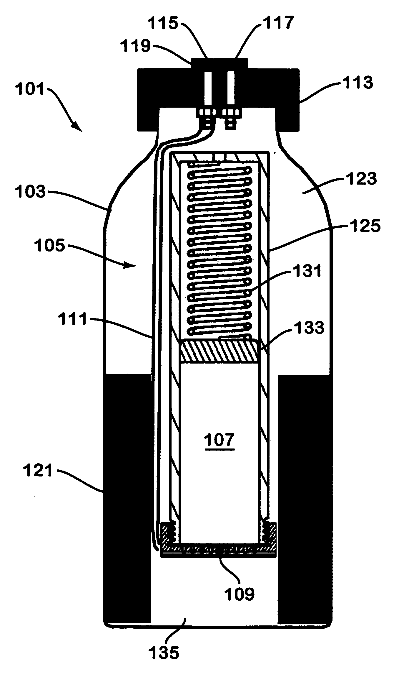
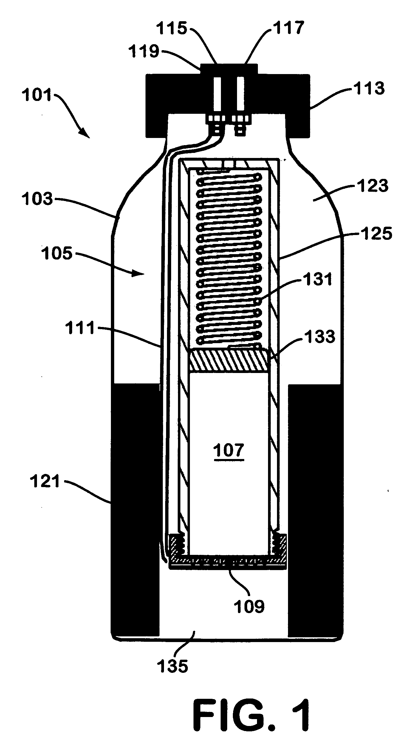
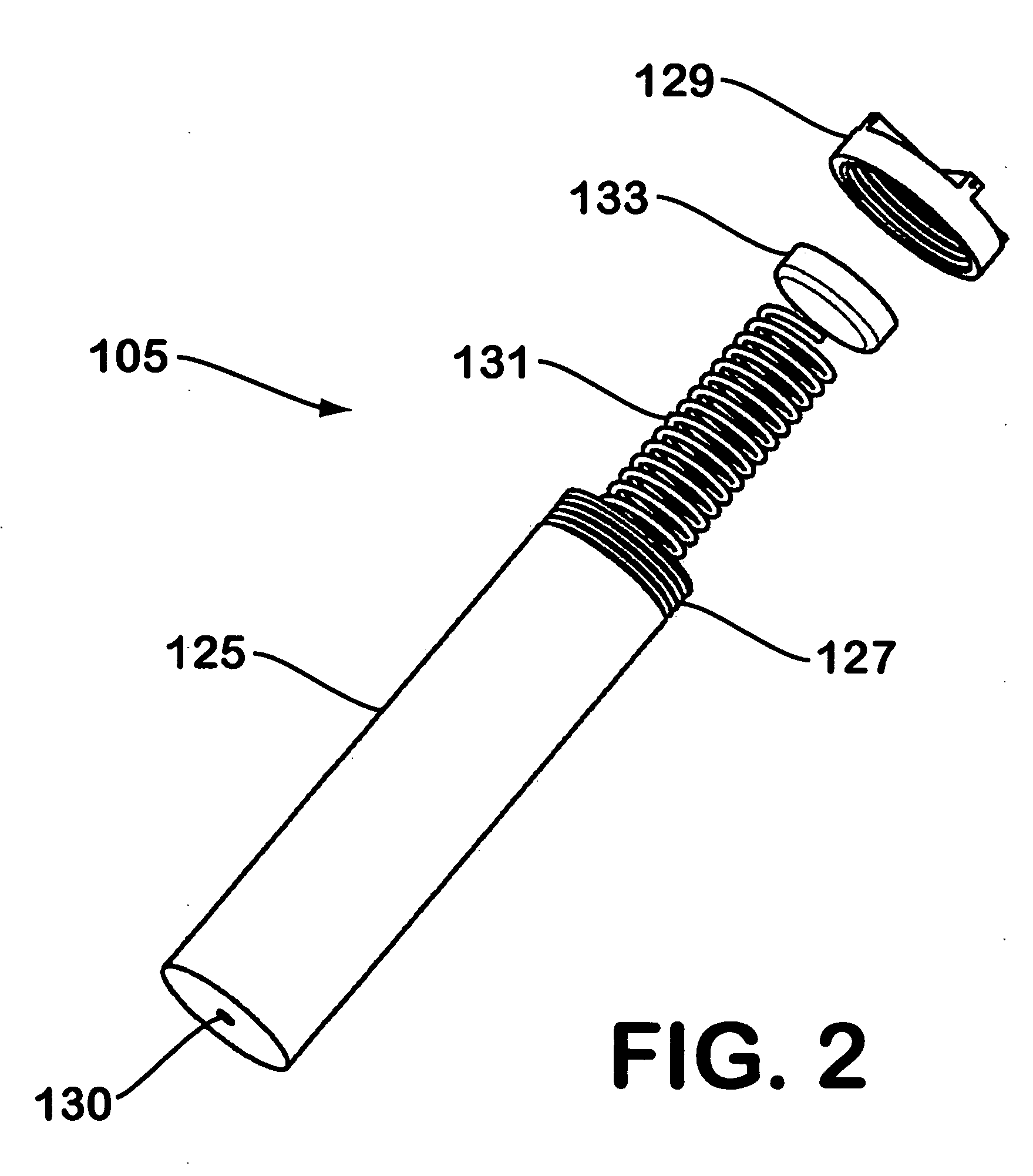
[0036]FIG. 3 illustrates a hydrogen generator made in accordance with the teachings herein. The hydrogen generator 201 of this embodiment is similar in most respects to the embodiment depicted in FIGS. 1-2. However, in this embodiment, the hydrogen gas evolved from the sodium borohydride pellet 107 is collected through the aperture 130 (see FIG. 2) provided in one end of the dispenser 105. In the particular embodiment depicted, a tube 141 is provided which connects aperture 130 to hydrogen outlet port 117 although, in some variations of this embodiment, the tube 141 may be omitted.
[0037] A further difference between the embodiment of FIG. 3 and the embodiment depicted in FIGS. 1-2 is the provision of a desiccating agent 143 in the spring-loaded portion of the dispenser. The desiccating agent 143 is disposed in the path of egress of the hydrogen gas as it flows from the reaction interface 109 and through the interior of the cylinder. 125 (see FIG. 2) of the hydride dispenser 105. Hen...
third embodiment
[0040]FIG. 4 illustrates a hydrogen generator made in accordance with the teachings herein. The hydrogen generator 301 of this embodiment is similar in most respects to the embodiment depicted in FIGS. 1-2. However, in the hydrogen generator of FIG. 3, the hydrogen-containing material is provided in the form of a bed 145 of particles. In the particular embodiment depicted, the particles are shown as being spherical particles of approximately equal dimensions. However, it will be appreciated that the particles may be of other shapes or mixtures of shapes, and may have various size distributions or size gradients.
[0041] One of the advantages of the use of a bed 145 of particles in the hydrogen generator 301 depicted in FIG. 4 is that the bed 145 contains a significant volume of empty space in the form of interstitial cavities that are present between the component particles. During operation, this space serves as a reservoir for generated hydrogen gas. Consequently, the overall dimens...
fourth embodiment
[0043]FIG. 5 depicts a hydrogen generator made in accordance with the teachings herein. In the hydrogen generator 401 of FIG. 5, the storage volume provided by the interstitial cavities is sufficiently large that the need for a housing external to the dispenser is entirely eliminated (put another way, the external housing is merged with the dispenser). In the embodiment depicted in FIG. 5, the plug 147 is sufficiently porous to allow the egress of spent hydrogen-containing material (e.g., hydrated sodium borate) therethrough, so that it can collect in the space occupied by the spring 131. The water delivery tube 111 is in open communication with at least the surface of the plug 147 that is in contact with the hydrogen-containing material 145 (the water delivery tube 111 is preferably coiled to permit free extension of the spring 131). Preferably, this surface is adapted to serve as a wicking element for water applied to it. In some embodiments, the opposing surface of the plug 147 m...
PUM
| Property | Measurement | Unit |
|---|---|---|
| hydrogen flow rate | aaaaa | aaaaa |
| temperature | aaaaa | aaaaa |
| temperature | aaaaa | aaaaa |
Abstract
Description
Claims
Application Information
 - R&D
- Intellectual Property
- Life Sciences
- Materials
- Tech Scout
- Unparalleled Data Quality
- Higher Quality Content
- 60% Fewer Hallucinations
Browse by: Latest US Patents, China's latest patents, Technical Efficacy Thesaurus, Application Domain, Technology Topic, Popular Technical Reports.
© 2025 PatSnap. All rights reserved.Legal|Privacy policy|Modern Slavery Act Transparency Statement|Sitemap|About US| Contact US: help@patsnap.com


