
Color filter and method of producing same

a color filter and film thickness technology, applied in the field of color filters, can solve the problems of increasing cost, increasing cost, and reducing yield, and achieve the effect of high-quality color filters and small film thickness changes

Inactive Publication Date: 2007-01-25
DAI NIPPON PRINTING CO LTD
View PDF0 Cites 8 Cited by
  • Summary
  • Abstract
  • Description
  • Claims
  • Application Information

AI Technical Summary

Benefits of technology

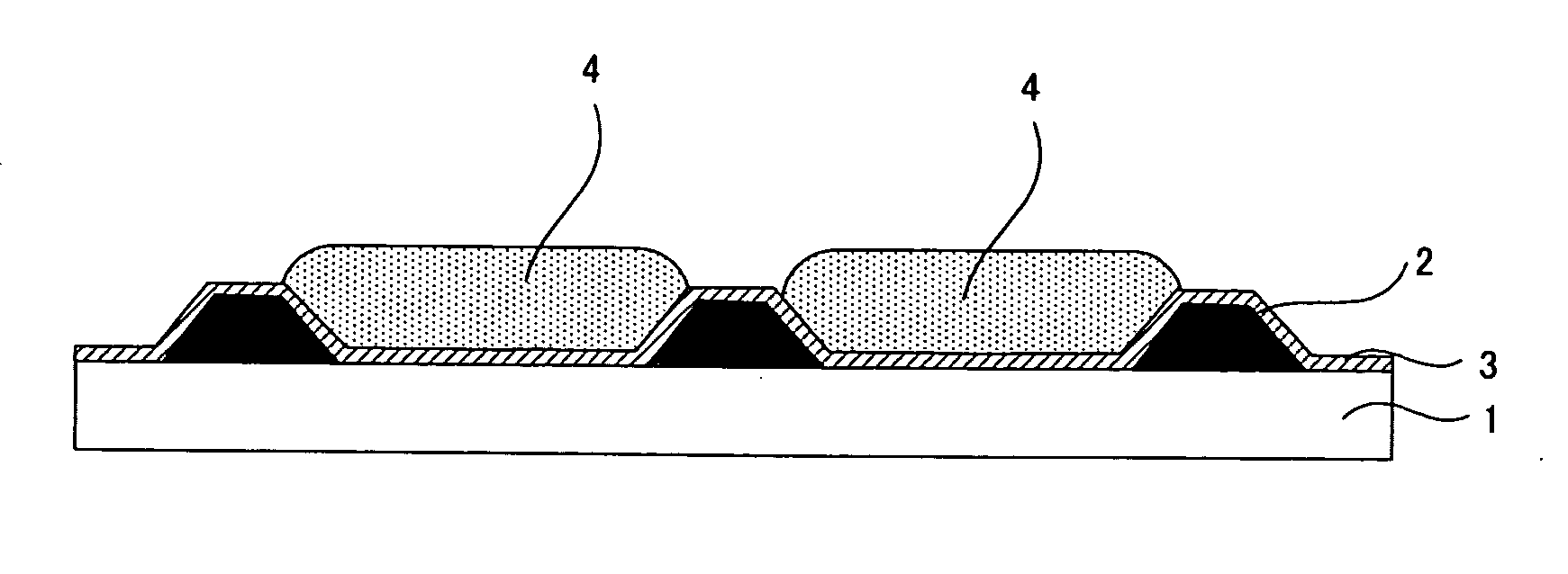
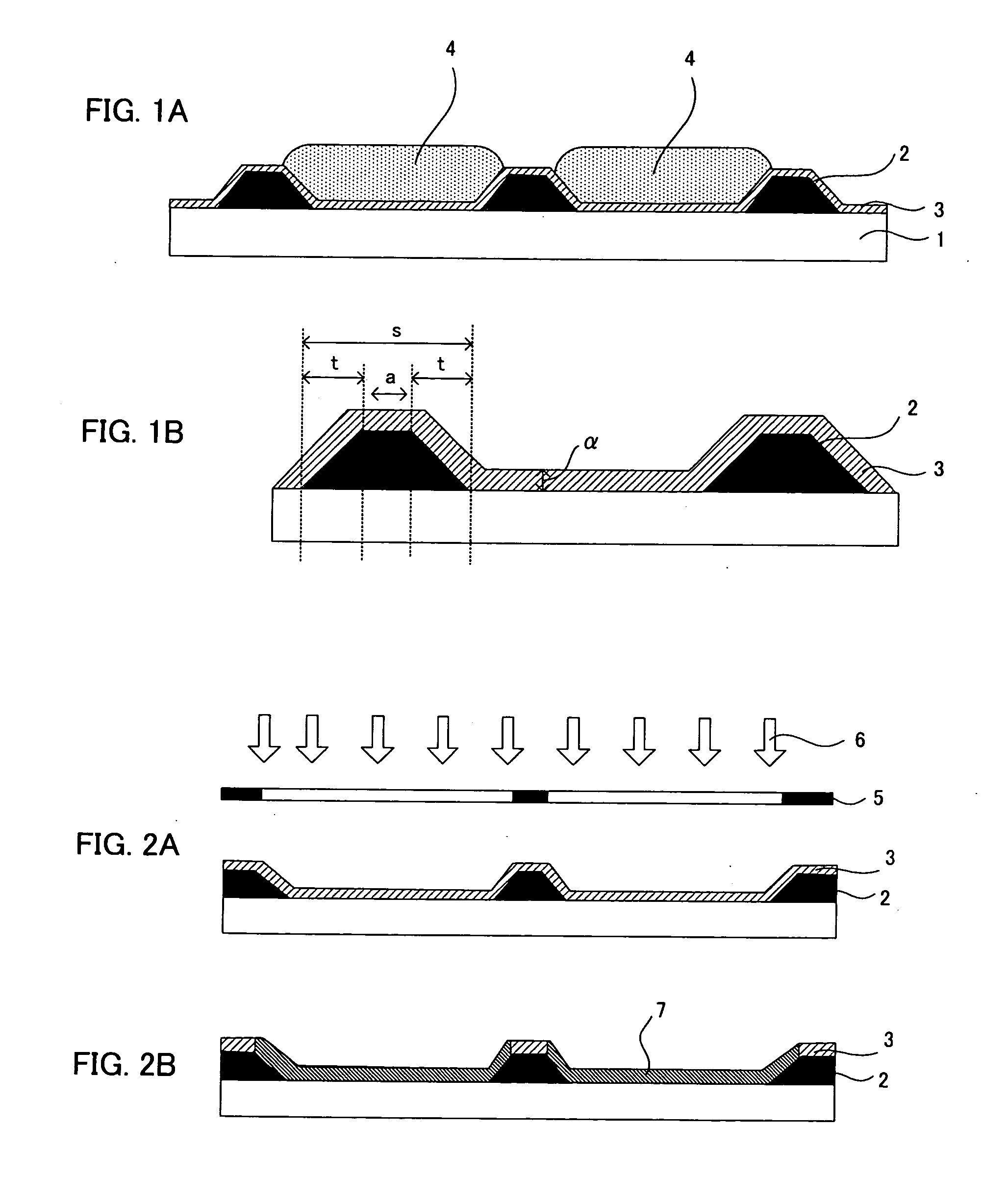
[0013] According to the invention, both the sides of the light shielding part are formed to satisfy the above-mentioned range and have the above-mentioned thin regions; therefore, a change in the film thickness of the light shielding part can be made small. For this reason, when a photocatalyst containing layer forming composition, for forming the photocatalyst containing layer, is applied to cover this light shielding part and then dried, the photocatalyst containing layer having the target film thickness can be formed in consistency with the shapes of the light shielding part. Thus, at the side faces of the light shielding part, and so forth, neither chipping nor unevenness in the film thickness is generated in the photocatalyst containing layer. In this way, the wettability of the surface of the photocatalyst containing layer can be evenly changed by the action of the photocatalyst accompanied by energy irradiation. This difference in the wettability in the photocatalyst containing layer surface is used to render the color filter a high-quality color filter wherein the colored layer having no white spots or color unevenness is easily formed.
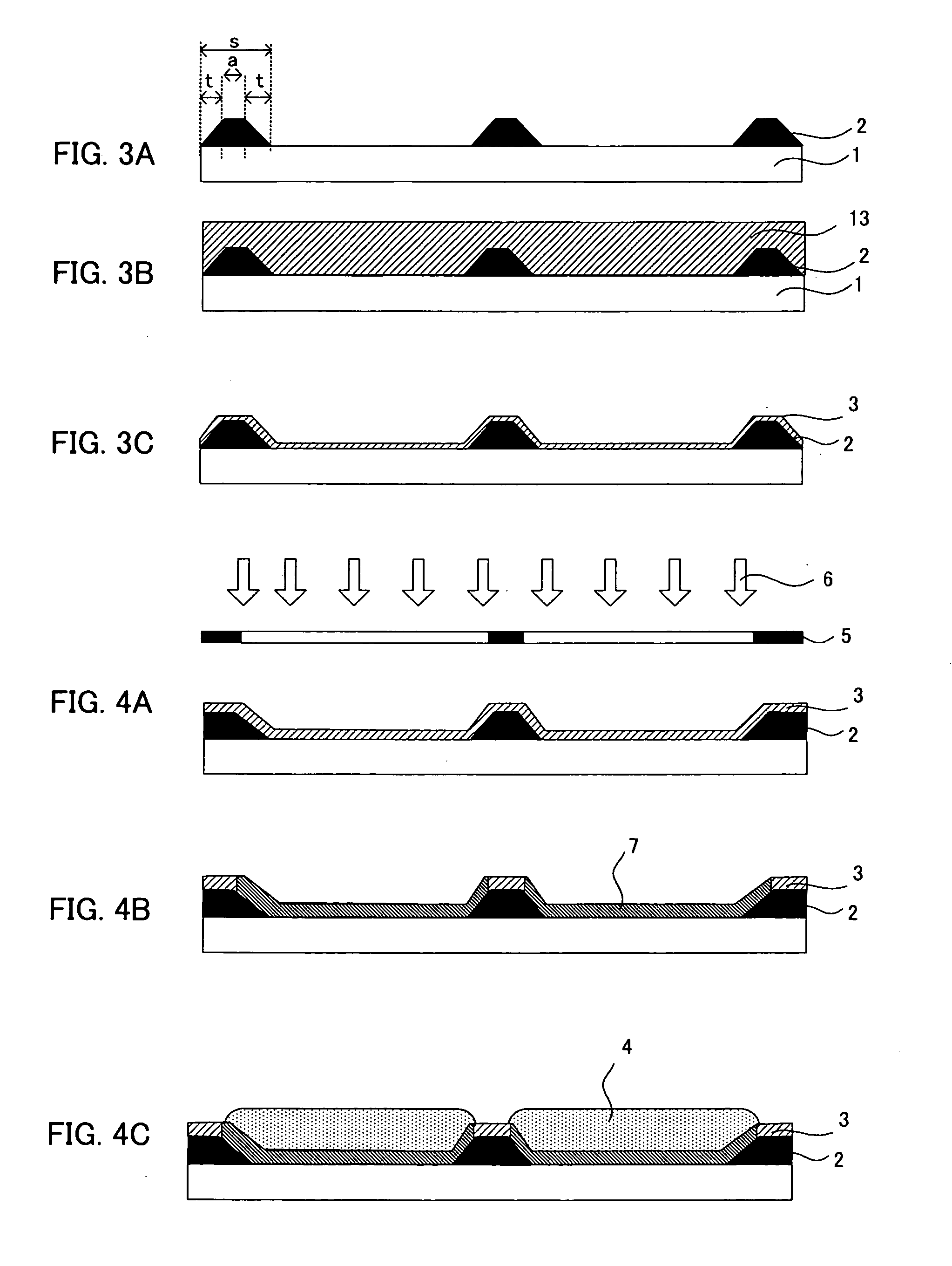
[0015] According to the invention, the light shielding part is formed to set the respective width of the thin region of the light shielding part into the above-mentioned range; therefore, a change in the film thickness of the light shielding part can be made small. For this reason, when the photocatalyst containing layer forming composition having the above-mentioned solid content concentration is applied into the above-mentioned film thickness and then dried, the photocatalyst containing layer can be formed in consistency with the shapes of the light shielding part. In this way, in the colored layer formed by using the property that the wettability in the surface of the photocatalyst containing layer is changed by the action of the photocatalyst accompanied by the energy irradiation to the photocatalyst containing layer, neither white spots nor color unevenness is generated. Thus, a high-quality color filter can be produced.

Problems solved by technology

However, the color liquid displays are expensive; therefore, a request that the cost should be reduced has been increasing.
However, according to the methods, in any case, the same step should be repeated for three times for coloring the three colors of R, G and B so that problems are involved in that the cost is increased or the yield is lowered due to the repetition of the steps.
Accordingly, when the photocatalyst containing layer forming composition is applied onto the base material with this resin light shielding part formed thereon and then dried, the photocatalyst containing layer is not easily formed in consistency with the shapes of the light shielding part in the case where the light shielding part has a shape perpendicular to the base material.
Consequently, the colored layer forming coating solution neither wets nor spreads sufficiently, so that such as white spots or color unevenness may be generated.

Method used


Image

  • Color filter and method of producing same
  • Color filter and method of producing same
  • Color filter and method of producing same

Examples


examples

[0138] The invention will be more specifically explained by way of an example and a comparative example.

example

1. Formation of the Light Shielding Part

[0139] A mixture of the below-mentioned composition was dissolved by heating at 90° C. and carrying out the centrifugal separation at 12,000 rpm, and then it was filtrated with a 1 μm glass filter. By adding 1% by weight of an ammonium dichromate as a cross linking agent to the obtained solution, a light shielding part forming coating solution for was prepared.

Carbon black (produced by Mitsubishi  4 parts by weightChemical Corporation #950)Polyvinyl alcohol (produced by Nippon0.7 part by weightSynthetic Chemical Industry Co., Ltd.,GOHSENOL AH-26)Ion exchange water95.3 parts by weight

[0140] A light shielding part pattern (resist pattern) was formed as below using the obtained light shielding part forming coating solution for the evaluation. First, the above-mentioned light shielding part forming coating solution was coated onto a sodium glass transparent base material with a spin coater and dried by a hot plate at 80° C. for 1 minute. The f...


PUM


Abstract

A main object of the present invention is to provide a high-quality color filter having a colored layer formed by use of a difference in wettability in the surface of a photocatalyst containing layer, wherein white spots and color unevenness are not present in the colored layer and a method for producing the same. To achieve the object, the present invention provides a color filter comprising: a base material; a light shielding part formed on the base material and containing a light shielding material and a resin; a photocatalyst containing layer formed to cover the base material and the light shielding part and containing a photocatalyst and an organopolysiloxane; and a colored layer formed on the photocatalyst containing layer in an opening part made in the light shielding part, wherein the widths of thin film regions of both sides each having a film thickness decreased in a tapered form from a central portion of the light shielding part are each in the range from 20 to 40% of the line width of the light shielding part, and the film thickness of the photocatalyst containing layer is in the range from 0.01 to 0.5 μm.

Description

BACKGROUND OF THE INVENTION [0001] 1. Field of the Invention [0002] The present invention relates to a color filter, obtained by coloring a colored layer with an ink jet method, suitable for a color liquid crystal display and the producing method of the same. [0003] 2. Description of the Related Art [0004] Recently, with the development of the personal computers, in particular, the development of the portable personal computers, demand for liquid crystal displays, especially for color liquid crystal displays tends to be increased. Further, bigger liquid crystal displays are in demand. However, the color liquid displays are expensive; therefore, a request that the cost should be reduced has been increasing. In particular, a request that the cost of their color filters, which accounts for a high ratio in the total cost, should be reduced has been raised. [0005] Such color filters, in general, comprise colored patterns of three primary colors of red (R), green (G) and blue (B) so that ...

Claims


Application Information

Patent Timeline
IPC IPC(8): B32B3/00
CPCY10T428/24612B32B3/00
Inventor YAMAMOTO, MANABU
Owner DAI NIPPON PRINTING CO LTD
Learn More