Plasma etching apparatus and particle removal method

a technology of etching apparatus and etching particles, which is applied in the direction of electrical apparatus, basic electric elements, electric discharge tubes, etc., can solve the problems of increasing the cost of the apparatus, and the structure of the apparatus complicated by the electrode, etc., so as to improve the efficiency and efficiency of the apparatus, the effect of quick dampening and easy follow-up of the flow

Inactive Publication Date: 2007-01-25
HITACHI HIGH-TECH CORP
View PDF10 Cites 16 Cited by
  • Summary
  • Abstract
  • Description
  • Claims
  • Application Information

AI Technical Summary

Benefits of technology

[0019] In an aspect of the particle removal method of the invention, discharge is performed at a pressure higher than the semiconductor substrate processing pressure. This pressure, which is set higher than normal processing pressure, more rapidly dampens the momentum that the particles have gained upon being stripped from the wall, and allows the particles to easily follow the flow of gas evacuation. A low pressure would increase the possibility that the stripping momentum may cause the particles to travel upstream into the region where the semiconductor substrate is processed. The higher the pressure, the more effectively the scattering of particles can be prevented. However, the pressure is subjected to the limitation of enabling discharge to occur, and depends on plasma generating methods. In one plasma etching apparatus, a suitable pressure is 20 to 50 Pa.
[0020] In this situation, a higher gas flow rate may advantageously increase the rate of evacuating the particles, but has a small effect of preventing the scattering of particles. Therefore increasing the pressure deserves a higher priority.

Problems solved by technology

In the method of cleaning a plasma etching apparatus as disclosed in Patent Document 1, addition of a cleaning electrode to the plasma etching apparatus increases apparatus cost due to an extra power supply and other components.
The electrode also complicates the structure of the apparatus.
Patent Document 1 does not sufficiently clarify how to design the apparatus to avoid residual particles in the interstices of the complicated structure.
The material of the components constituting the electrode still requires consideration of metal contamination and consumption cost.

Method used


Image

  • Plasma etching apparatus and particle removal method
  • Plasma etching apparatus and particle removal method
  • Plasma etching apparatus and particle removal method

Examples


Embodiment Construction

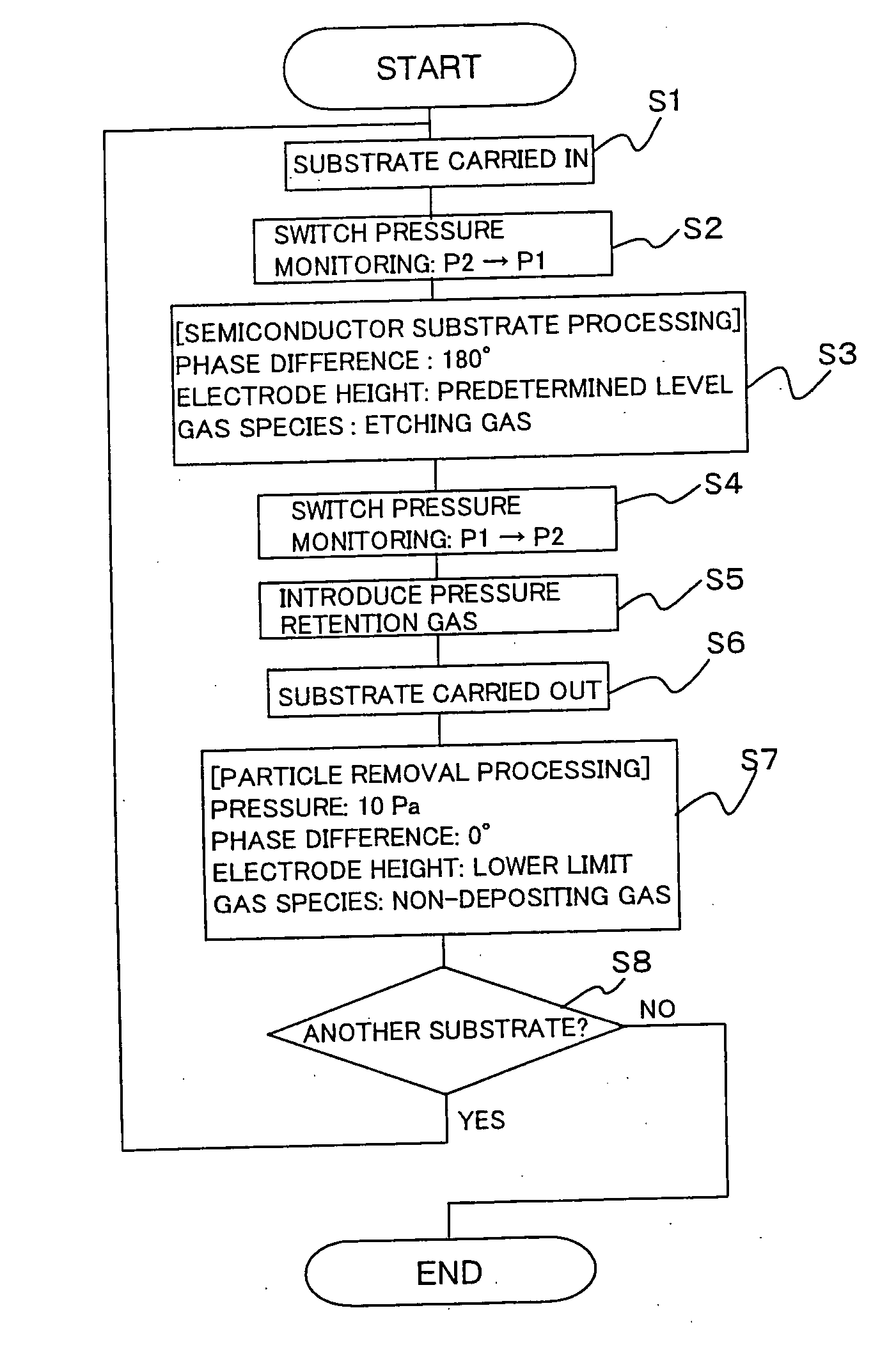
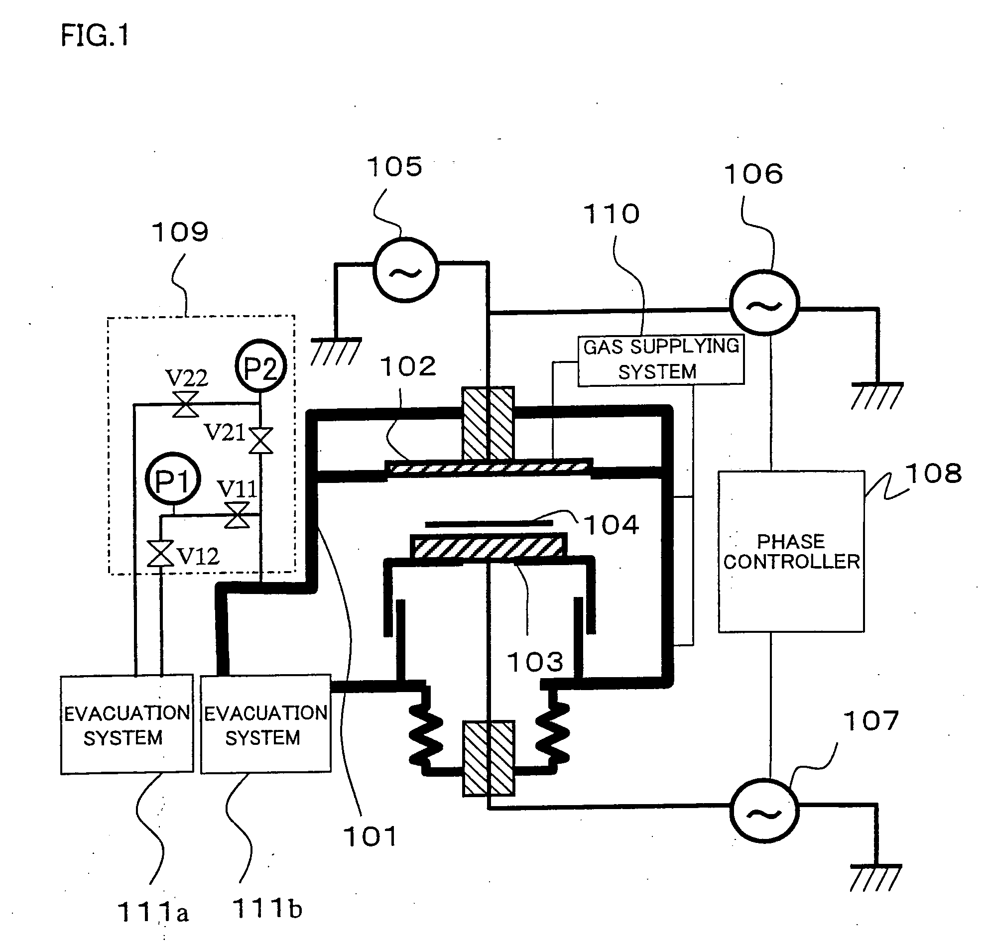
[0030] An embodiment of the invention will now be described with reference to the drawings. FIG. 1 shows a schematic view of a plasma etching apparatus according to the invention. The plasma etching apparatus according to the invention comprises an upper antenna 102 and a lower electrode 103 opposed thereto in a processing chamber 101 that can be evacuated. A semiconductor substrate 104 can be mounted on the lower electrode 103. The apparatus further comprises a 200 MHz source RF power supply 105 and an 800 kHz antenna RF power supply 106 for plasma generation, and an 800 kHz lower electrode RF power supply 107. The apparatus also comprises a phase controller 108 for controlling the phase of antenna RF power and lower electrode RF power. The lower electrode 103 is designed so as to be moved vertically. The plasma etching apparatus further includes a pressure monitoring system 109 for monitoring the pressure in the processing chamber 101, a gas supplying system 110 for supplying gas ...


PUM


Abstract

The invention provides a particle removal method for a plasma processing apparatus, the method easily removing particles in the chamber up to its lower part. In a plasma etching apparatus including an upper antenna, a lower electrode, pressure gauges P1 and P2, gas introducing means, evacuating means, and phase controlling means for controllably applying RF power at a common frequency to the upper antenna and the lower electrode and for controlling phase of the RF power between equal phase and opposite phase, the particle removal method comprises: during a semiconductor substrate processing, applying RF power to the upper antenna and the lower electrode in opposite phase of voltage; and when the semiconductor substrate is not processed, performing discharge in the presence of non-depositing gas, applied power for the upper antenna and for the lower electrode being in equal phase of voltage and having a voltage amplitude of 100 V or more, and the height of the lower electrode being lower than the height during the semiconductor substrate processing.

Description

[0001] The present application is based on and claims priority of Japanese patent application No. 2005-208869 filed on Jul. 19, 2005, the entire contents of which are hereby incorporated by reference. BACKGROUND OF THE INVENTION [0002] 1. Field of the Invention [0003] This invention relates to a plasma processing apparatus for use in the field of semiconductor manufacture, and more particularly to a plasma processing method capable of reducing particles. [0004] 2. Description of the Related Art [0005] Generally, in many plasma etching apparatuses, special functionality for removing particles is not provided. However, there is disclosed a method of cleaning a plasma CVD film forming apparatus by local discharge with a special electrode called “cleaning electrode” (see, e.g., Japanese Laid-Open Patent Application 2002-57110, hereinafter referred to as Patent Document 1). In addition, there is disclosed a method of efficiently removing particles from a plasma processing chamber by decr...

Claims


Application Information

Patent Timeline
Patent Type & Authority Applications(United States)
IPC IPC(8): H01L21/302H01L21/461
CPCH01J37/321H01J37/32862H01J37/32568
Inventor TAMURA, TOMOYUKIMAEDA, KENJIKOBAYASHI, HIROYUKI
Owner HITACHI HIGH-TECH CORP
Why Eureka
Try Eureka