Specialized, tapered bolts for rear axle shafts

a technology of tapered bolts and rear axles, applied in the direction of fastening means, screws, control devices, etc., can solve the problems of increasing the cost of manufacturing and assembling so many specialized fastener components, reducing the difficulty associated with the installation, and reducing the cost of both hardware and assembly. , the effect of reducing the difficulty

a technology of tapered bolts and rear axles, applied in the direction of fastening means, screws, control devices, etc., can solve the problems of increasing the cost of manufacturing and assembling so many specialized fastener components, reducing the difficulty associated with the installation, and reducing the cost of both hardware and assembly. , the effect of reducing the difficulty

US20070023226A1Inactive Publication Date: 2007-02-01INT TRUCK INTPROP LLC

Image

  • Specialized, tapered bolts for rear axle shafts
  • Specialized, tapered bolts for rear axle shafts
  • Specialized, tapered bolts for rear axle shafts

Examples


Embodiment Construction

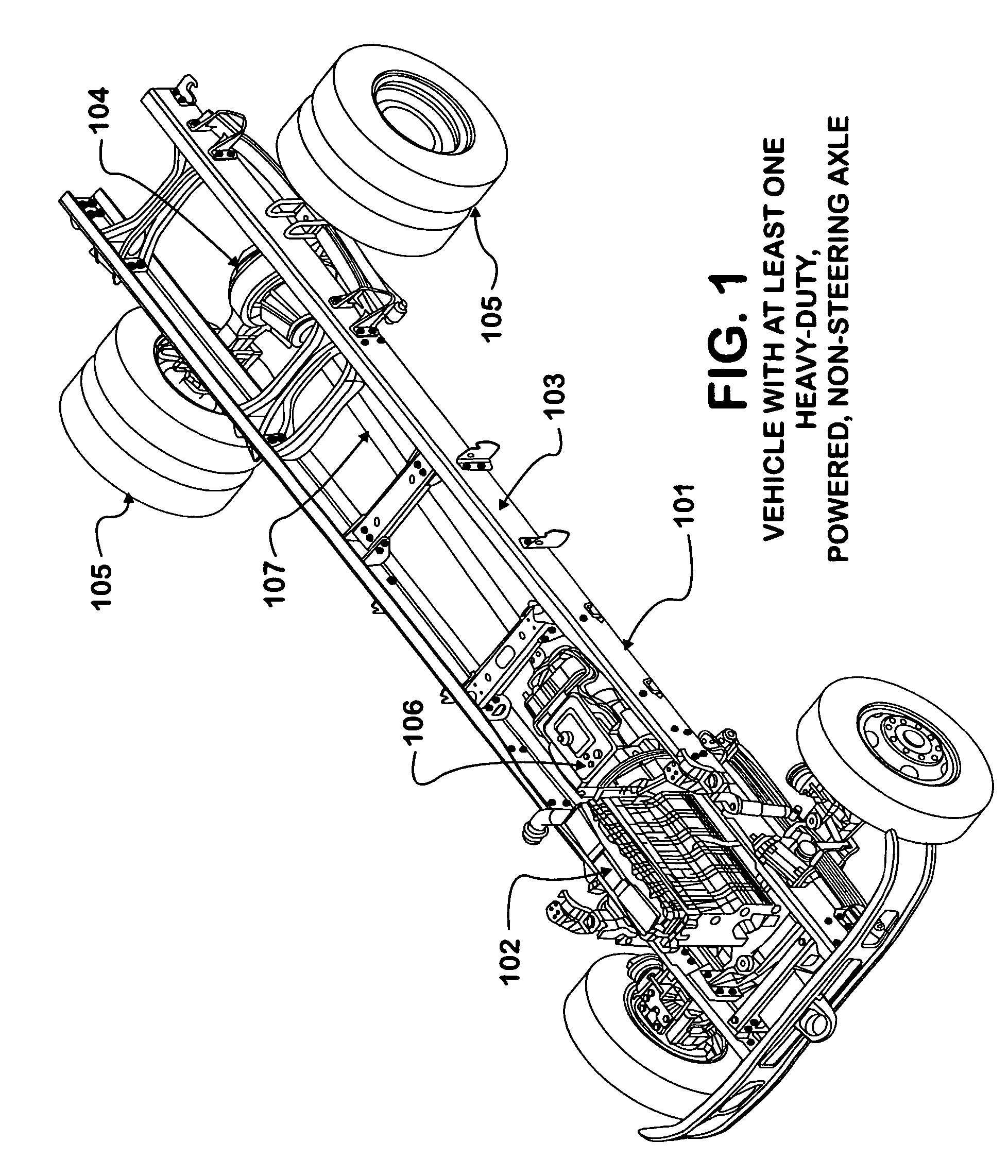
[0027] The vehicle 101 shown in FIG. 1 has an engine 102 attached to a chassis 103. The vehicle 101 also has at least one heavy-duty, powered, non-steering (full-floating) axle 104 attached to chassis 103. The heavy-duty, powered, non-steering (full-floating) axle 104 is provided with wheel and tire assemblies 105. The engine 102 provides power to a transmission 106, which in turn provides power to a propeller shaft 107. The propeller shaft 107 thereby provides power to the heavy-duty, powered, non-steering (full-floating) axle 104 and to wheel and tire assemblies 105.

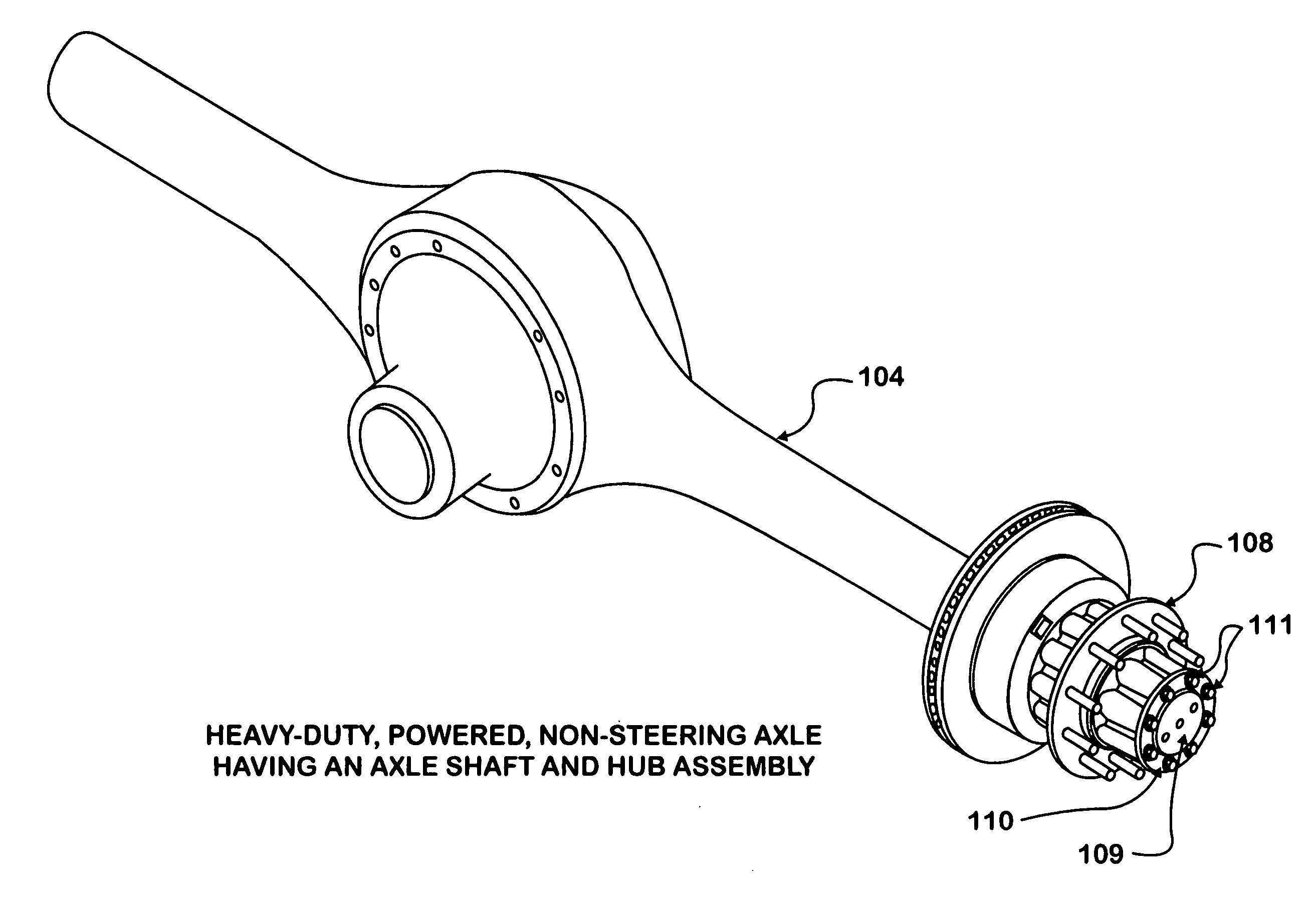
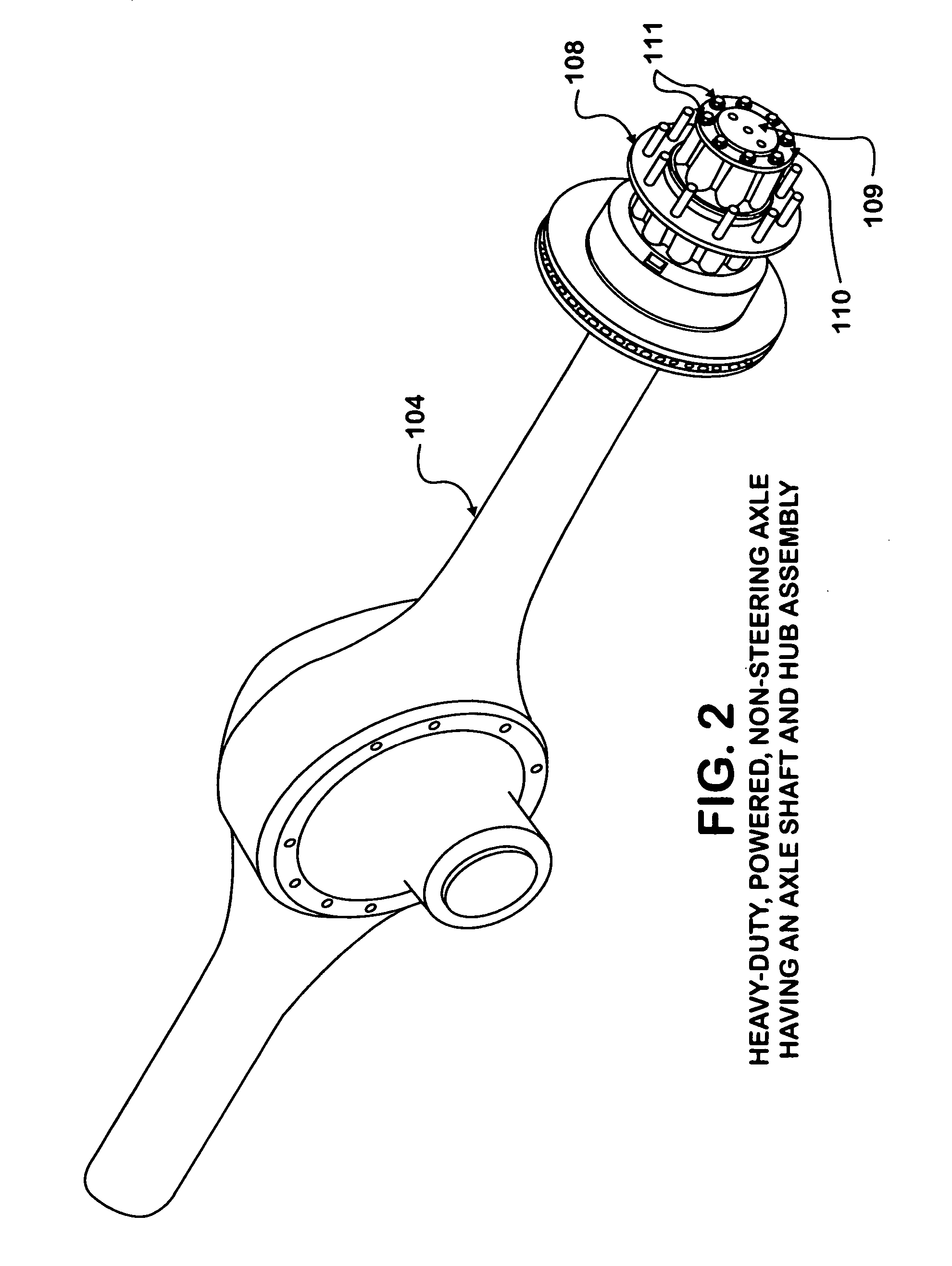
[0028]FIG. 2 shows a heavy-duty, powered, non-steering (full-floating) axle 104, similar to the heavy-duty, powered, non-steering (full-floating) axle 104 appearing attached to chassis 103 in FIG. 1. The heavy-duty, powered, non-steering (full-floating) axle 104 in FIG. 2 is provided with a hub assembly 108 and an axle shaft 109 having an axle shaft flange 110. The axle shaft flange 110 is attached to hub assembly 108...


PUM


Abstract

A tapered-head bolt for use in attaching axle shafts to hub assemblies in heavy-duty, powered, non-steering (full-floating) axles. Use of the tapered-head bolt eliminates the deficiencies and complexity associated with the current use of studs, cone-nuts, cone-washers, and / or lock nuts.

Description

BACKGROUND OF INVENTION [0001] This invention relates to fasteners used on an axle assembly for a ground traveling vehicle. Specifically, it relates to the fasteners used to attach the axle shafts of a heavy-duty driving rear axle to the hub assemblies. In lieu of the studs, cone-nuts, cone-washers, lock washers, and / or lock nuts that are conventionally utilized, a single set of specialized, tapered-head bolts securely retain the flanges at the end of the axle shafts to the hub castings. SUMMARY [0002] Mobile ground traveling vehicles are commonly configured with one or more wheel and axle assemblies. These axles are provided in a large number of different types, depending on whether the axle is powered or non-powered, whether the axle is steering or non-steering, and the weight bearing capacity of the axle. Powered, non-steering axles consist of a hollow tube or housing with an enclosure near its center for containing a differential gear. This differential gear receives power from ...

Claims


Application Information

Patent Timeline
01 Feb 2007
Publication
US20070023226A1
IPC
B60K17/00; F16B23/00
CPC
F16B35/06; F16B23/0038
Inventors
HAWASH, SUHEAL N.; GALLMEYER, HENRY A.