Bi-direction rapid action electrostatically actuated microvalve

a micro-valve, electrostatically actuated technology, applied in the field of microfluidics, can solve the problems of increasing the life of the device, achieve the effect of reducing the film squeezing pressure of the membrane electrode, quick actuation, and low surface charge trapping

Pending Publication Date: 2007-02-01
THE BOARD OF TRUSTEES OF THE UNIV OF ILLINOIS
View PDF35 Cites 22 Cited by
  • Summary
  • Abstract
  • Description
  • Claims
  • Application Information

AI Technical Summary

Benefits of technology

[0020] A preferred embodiment bi-directional electrostatic microvalve of the invention includes a membrane electrode that is controlled by application of voltage to fixed electrodes disposed on either side of the membrane electrode. Dielectric insulating layers separate the electrodes. One of the fixed electrodes defines a microcavity. Microfluidic channels formed into the electrodes provide fluid to the microcavity. A central pad defined in the microcavity places a portion of the second electrode close to the membrane electrode to provide a quick actuation while the microcavity reduces film squeezing pressure of the membrane electrode.
[0021] In preferred embodiment microvalves, low surface charge trapping and low surface energycoatings coat low bulk charge trapping dielectric on the electrodes. An example preferred low surface charge trapping layer is a thin nitride layer. An example preferred low surface energy layer is a fluorocarbon film made from cross-linked carbon di-fluoride monomers or surface monolayers made from fluorocarbon terminated silanol compounds. Layer combinations in preferred embodiments limit charge trapping and other problems and increase device lifetime operation.

Problems solved by technology

Layer combinations in preferred embodiments limit charge trapping and other problems and increase device lifetime operation.

Method used


Image

  • Bi-direction rapid action electrostatically actuated microvalve
  • Bi-direction rapid action electrostatically actuated microvalve
  • Bi-direction rapid action electrostatically actuated microvalve

Examples


Embodiment Construction

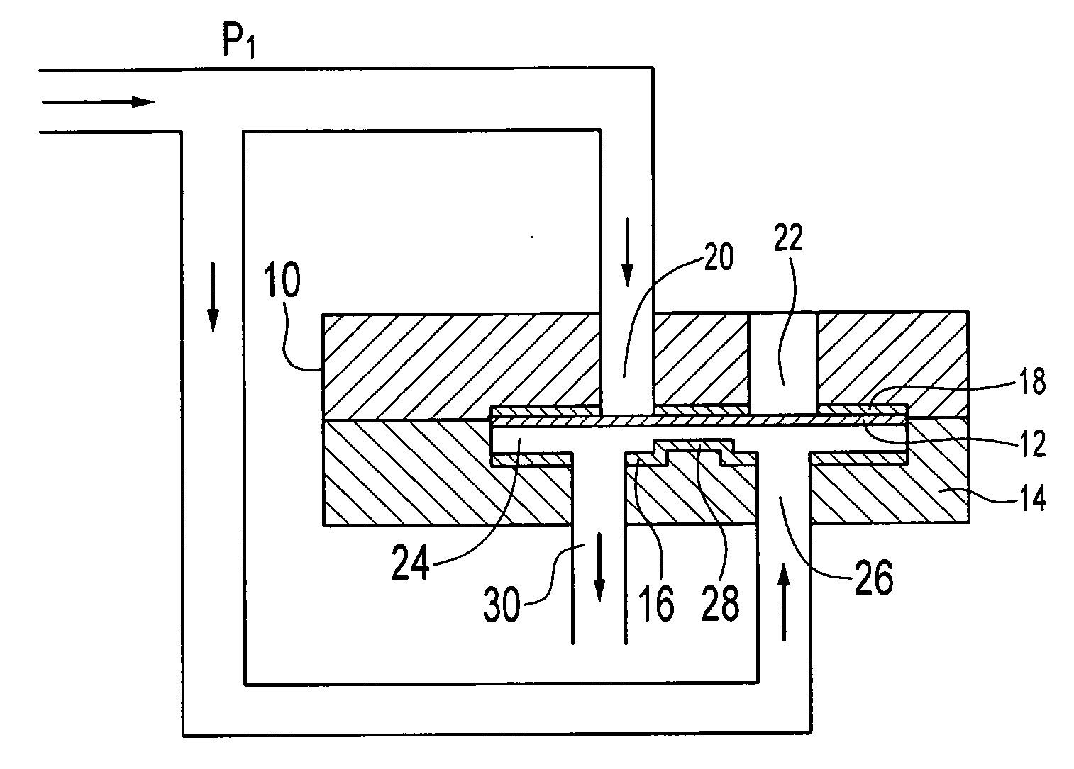
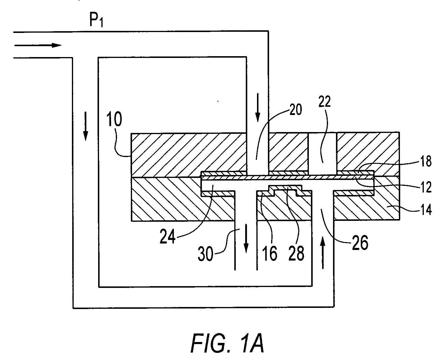
[0039] A preferred embodiment bidirectional electrostatic microvalve of the invention includes a membrane electrode that is controlled by application of voltage to fixed electrodes disposed on either side of the membrane electrode. Dielectric insulating layers separate the electrodes. One of the fixed electrodes defines a microcavity. Microfluidic channels formed into the electrodes provide fluid to the microcavity. A central pad defined in the microcavity places a portion of the second electrode close to the membrane electrode to provide a quick actuation while the microcavity reduces film squeezing pressure of the membrane electrode.

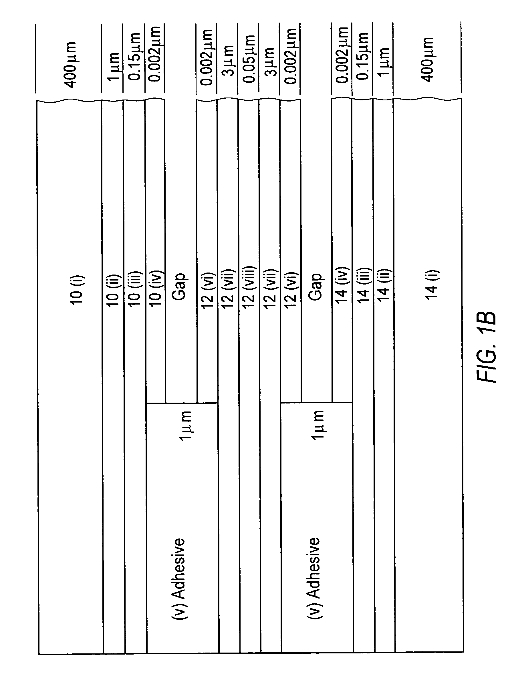
[0040] In preferred embodiment microvalves, low surface charge trapping and low surface energy coatings coat low bulk charge dielectric layers. In preferred embodiments, thin silicon nitride coatings provide low surface charge trapping dielectric. For low surface energy, fluorocarbon films made from cross-linked carbon di-fluoride monomers or surface ...


PUM


Abstract

A bi-directional electrostatic microvalve includes a membrane electrode that is controlled by application of voltage to fixed electrodes disposed on either side of the membrane electrode. Dielectric insulating layers separate the electrodes. One of the fixed electrodes defines a microcavity. Microfluidic channels formed into the electrodes provide fluid to the microcavity. A central pad defined in the microcavity places a portion of the second electrode close to the membrane electrode to provide a quick actuation while the microcavity reduces film squeezing pressure of the membrane electrode. In preferred embodiment microvalves, low surface energy and low surface charge trapping coatings, such as fluorocarbon films made from cross-linked carbon di-fluoride monomers or surface monolayers made from fluorocarbon terminated silanol compounds coatings coat the electrode low bulk charge trapping dielectric layers limit charge trapping and other problems and increase device lifetime operation.

Description

PRIORITY CLAIM [0001] Applicants claim priority benefits under 35 U.S.C. §119 on the basis of Patent Application No. 60 / 702,972, filed Jul. 27, 2005.STATEMENT OF GOVERNMENT INTEREST [0002] This invention was made with Government assistance under Contract No. FA8650-04-1-7121 awarded by the Defense Advanced Research Projects Agency (DARPA). The Government has certain rights in this invention.FIELD OF THE INVENTION [0003] The invention concerns microfluidics. The invention provides an electrostatically actuated microvalve that can be used in a wide variety of microfluidic applications, e.g., chemical analysis, pre-concentrators, micro-total analysis system (μTAS), gas / liquid sample injection, mixing, lab-on-a chip, micropumps and compressors, etc. BACKGROUND [0004] Microvalves are the subject of continuing research. Microvalves generally utilize microelectromechanical systems (MEMS) technology to control fluid flow in microfluidic systems. Microvalves have been variously used in chemi...

Claims


Application Information

Patent Timeline
Patent Type & Authority Applications(United States)
IPC IPC(8): F16K31/02
CPCF16K31/025F16K99/0001F16K99/0005F16K99/0015F16K2099/0084F16K99/0051F16K2099/0074F16K2099/008F16K99/0034F16K31/02
Inventor SHANNON, MARK A.BAE, BYUNGHOONMASEL, RICHARD I.
Owner THE BOARD OF TRUSTEES OF THE UNIV OF ILLINOIS
Why Eureka
Try Eureka