Method and apparatus for conducting RAMAN spectroscopy using a remote optical probe

a technology of raman spectroscopy and optical probe, which is applied in the direction of spectrometry/spectrophotometry/monochromators, optical radiation measurement, instruments, etc., can solve the problems of increasing the cost of optical probe heads, generating relative broadband spurious background noise signals, and significantly less practical disposable optical probe heads. achieve the effect of maintaining sensitivity of the system, reducing the probability of raman spectroscopy being carried out, and reducing the number of spur

Active Publication Date: 2007-02-01
AHURA CORP
View PDF31 Cites 18 Cited by
  • Summary
  • Abstract
  • Description
  • Claims
  • Application Information

AI Technical Summary

Benefits of technology

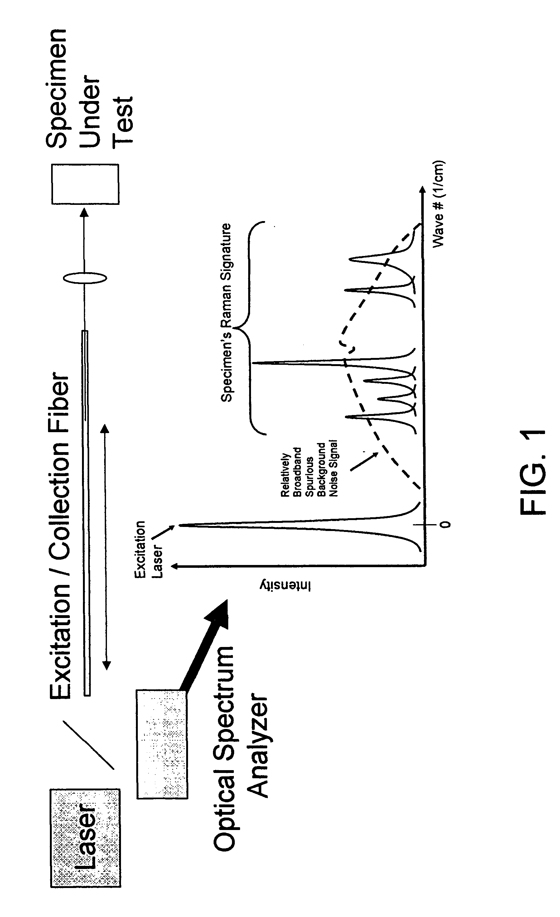
[0020] In one preferred embodiment of the present invention, there is provided an improved Raman spectroscopy system which comprises an improved optical probe assembly utilizing a single light guide to both deliver pump light to the specimen and to collect the Raman signature from the specimen, with the single light guide being constructed so as to minimize any relatively broadband spurious background noise signal when delivering pump light to the specimen. As a result, the signal-to-noise ratio of the Raman signature will remain robust even where only a single light guide is used, thereby maintaining sensitivity of the system and enhancing specimen selectivity.
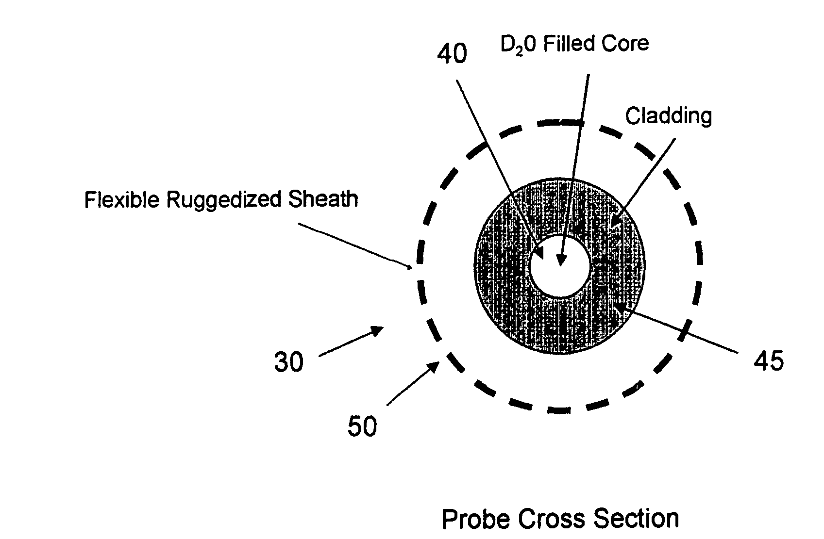
[0021] In one preferred form of the invention, the optical probe assembly preferably comprises an optical guide comprising a core region and a surrounding cladding region, wherein the core region is constructed so as to minimize the creation of any relatively broadband spurious background noise signal when passing the pump light, and the cladding region is constructed so as to satisfy wave guiding reflection requirements.
[0023] In another form of the present invention, there is provided an optical probe assembly for conveying Raman pump light to a specimen and for conveying a Raman signature from the specimen to an optical spectrum analyzer, the optical probe assembly comprising a light guide, wherein the light guide comprises a core region and a surrounding cladding region, wherein the core region is constructed so as to minimize the creation of a relatively broadband spurious background noise signal when conveying the Raman pump light to the specimen, and the cladding region is constructed so as to satisfy the wave guiding reflection requirements of the Raman pump light and the Raman signature.
[0026] an optical probe assembly for conveying the Raman pump light to a specimen and for conveying a Raman signature from the specimen to an optical spectrum analyzer, the optical probe assembly comprising a light guide, wherein the light guide comprises a core region and a surrounding cladding region, wherein the core region is constructed so as to minimize the creation of a relatively broadband spurious background noise signal when conveying the Raman pump light to the specimen, and the cladding region is constructed so as to satisfy wave guiding reflection requirements of the Raman pump light and the Raman signature; and
[0030] conveying the Raman pump light through an optical probe assembly to a specimen and conveying a Raman signature from the specimen through the optical probe assembly to an optical spectrum analyzer, the optical probe assembly comprising a light guide, wherein the light guide comprises a core region and a surrounding cladding region, wherein the core region is constructed so as to minimize the creation of a relatively broadband spurious background noise signal when conveying the Raman pump light to the specimen, and the cladding region is constructed so as to satisfy wave guiding reflection requirements of the Raman pump light and the Raman signature; and

Problems solved by technology

However, the amorphous nature of the glass used in a conventional optical fiber (and, specifically, the non-linear coefficients of the optical fiber's refractive index), together with the high optical power of the pump laser, typically causes a relatively broadband spurious background noise signal, having a significant intensity, to be generated as the pump light travels through the fiber.
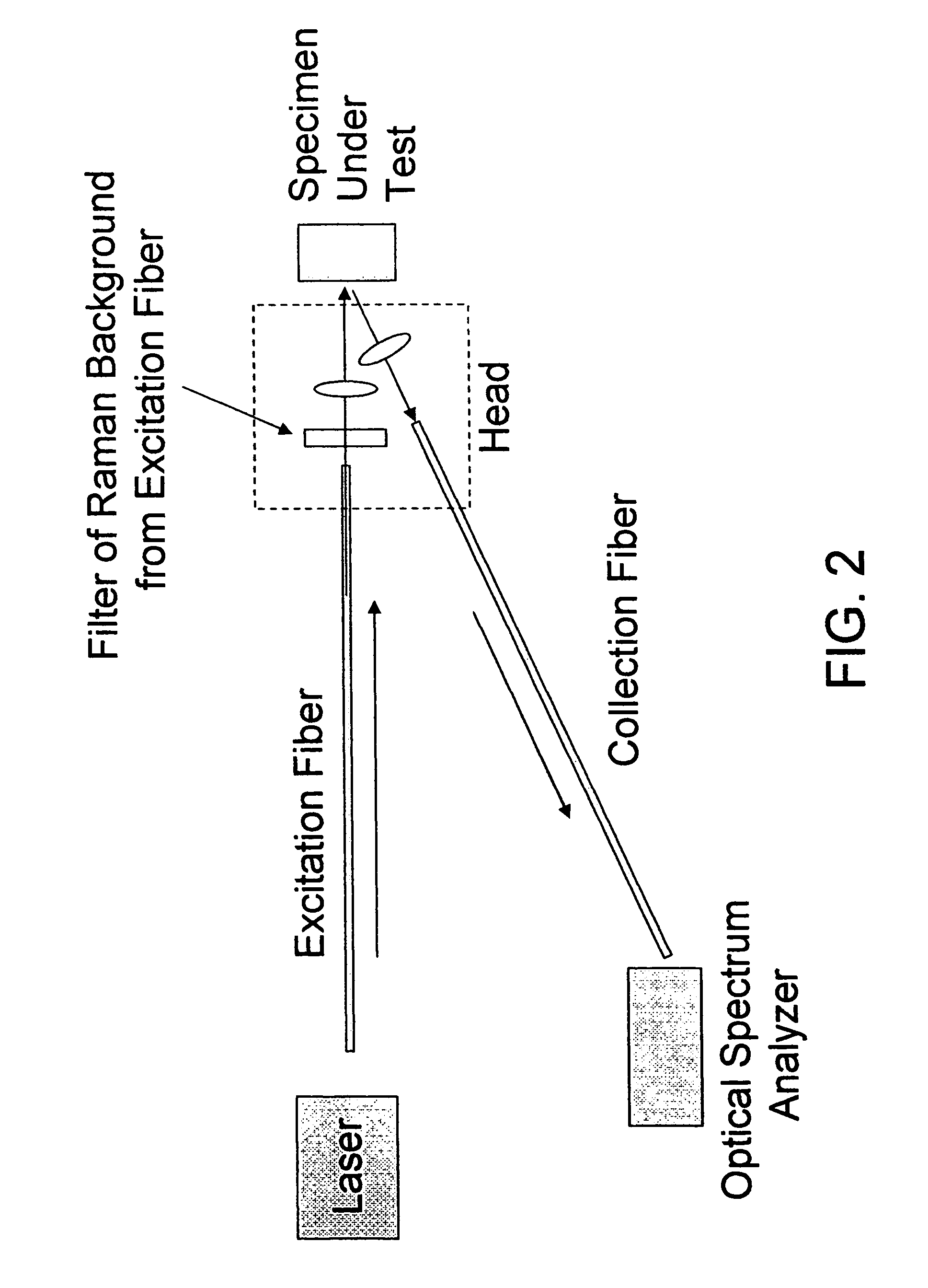
In any case, the complexity of a two fiber and filter construction (i.e., excitation fiber, filter and collection fiber) increases the cost of the optical probe head and makes a disposable optical probe head significantly less feasible.

Method used


Image

  • Method and apparatus for conducting RAMAN spectroscopy using a remote optical probe
  • Method and apparatus for conducting RAMAN spectroscopy using a remote optical probe
  • Method and apparatus for conducting RAMAN spectroscopy using a remote optical probe

Examples


Embodiment Construction

[0038] Looking first at FIGS. 3 and 4, there is shown a novel Raman spectroscopy system 5 for conducting remoter sensing of a specimen 10. Novel Raman spectroscopy system 5 generally comprises a laser 15 for generating the Raman pump signal, an optical probe assembly 20 for (i) delivering the Raman pump signal to the specimen, and (ii) gathering the Raman signature from the specimen, and an optical spectrum analyzer 25 for analyzing the Raman signature of the specimen so as to identify and characterize the specimen.

[0039] Laser 15 may comprise any laser suitable for use in Raman spectroscopy. By way of example but not limitation, laser 15 may comprise one or more >300 mW, 785 nm semiconductor lasers with limited linewidths (e.g.,˜2 cm−1). The output of laser 15 is delivered into the optical probe assembly 20 for delivery to the specimen.

[0040] Optical probe assembly 20 generally comprises a light guide 30 for delivering excitation (pump) light to the specimen and for collecting th...


PUM

PropertyMeasurementUnit
wavelength rangeaaaaaaaaaa
capillary structureaaaaaaaaaa
optical indexaaaaaaaaaa

Abstract

An optical probe assembly for conveying Raman pump light to a specimen and for conveying a Raman signature from the specimen to an optical spectrum analyzer, the optical probe assembly comprising a light guide, wherein the light guide comprises a core region and a surrounding cladding region, wherein the core region is constructed so as to minimize the creation of a relatively broadband spurious background noise signal when conveying the Raman pump light to the specimen, and the cladding region is constructed so as to satisfy the wave guiding reflection requirements of the Raman pump light and the Raman signature. A Raman spectroscopy system comprising: a laser for producing Raman pump light; an optical probe assembly for conveying the Raman pump light to a specimen and for conveying a Raman signature from the specimen to an optical spectrum analyzer, the optical probe assembly comprising a light guide, wherein the light guide comprises a core region and a surrounding cladding region, wherein the core region is constructed so as to minimize the creation of a relatively broadband spurious background noise signal when conveying the Raman pump light to the specimen, and the cladding region is constructed so as to satisfy wave guiding reflection requirements of the Raman pump light and the Raman signature; and an optical spectrum analyzer for receiving the Raman signature of a specimen and identifying and characterizing the specimen based upon the spectrum of the Raman signature. A method for conducting Raman spectroscopy comprising: producing Raman pump light; conveying the Raman pump light through an optical probe assembly to a specimen and conveying a Raman signature from the specimen through the optical probe assembly to an optical spectrum analyzer, the optical probe assembly comprising a light guide, wherein the light guide comprises a core region and a surrounding cladding region, wherein the core region is constructed so as to minimize the creation of a relatively broadband spurious background noise signal when conveying the Raman pump light to the specimen, and the cladding region is constructed so as to satisfy wave guiding reflection requirements of the Raman pump light and the Raman signature; and identifying and characterizing the specimen based upon the spectrum of the Raman signature.

Description

REFERENCE TO PENDING PRIOR PATENT APPLICATION [0001] This patent application: [0002] (i) is a continuation-in-part of pending prior U.S. patent application Ser. No. 10 / 826,706, filed Apr. 16, 2004 by Kevin J. Knopp et al. for RAMAN SPECTROSCOPY SYSTEM AND METHOD AND SPECIMEN HOLDER THEREFOR (Attorney's Docket No. AHURA-1116); [0003] (ii) is a continuation-in-part of pending prior U.S. patent application Ser. No. 11 / 117,940, filed Apr. 29, 2005 by Peidong Wang et al. for METHOD AND APPARATUS FOR CONDUCTING RAMAN SPECTROSCOPY (Attorney's Docket No. AHURA-2230); and [0004] (iii) claims benefit of pending prior U.S. Provisional Patent Application Ser. No. 60 / 698,270, filed Jul. 11, 2005 by Kevin J. Knopp et al. for DISPOSABLE OPTICAL PROBE FOR RAMAN SPECTROSCOPY (Attorney's Docket No. AHURA-36 PROV). [0005] The three above-identified patent applications are hereby incorporated herein by reference. FIELD OF THE INVENTION [0006] This invention relates to methods and apparatus for identify...

Claims


Application Information

Patent Timeline
Patent Type & Authority Applications(United States)
IPC IPC(8): G01J3/44G01N21/65
CPCG01J3/02G01J3/0218G02B6/032G01N21/65G01N2021/656G01J3/0297
Inventor KNOPP, KEVIN J.ZHU, LEYUNVAKHSHOORI, DARYOOSH
Owner AHURA CORP
Why Eureka
Try Eureka