Optical switch router

a switch router and optical switch technology, applied in the field of optical networking, can solve the problems of adding complexity to the device, adding substantial delay to the communication path, and often not being able to process information,

Inactive Publication Date: 2007-02-01
NORTEL NETWORKS INC +1
View PDF9 Cites 7 Cited by
  • Summary
  • Abstract
  • Description
  • Claims
  • Application Information

AI Technical Summary

Benefits of technology

[0011] One advantage of such an optical switch router over a traditional router is that the optical switch router does not perform optical-electrical-optical conversions in order to pass an optical data stream through from an incoming optical fiber to an outgoing optical fiber. Instead, the optical data stream is passed through unchanged in optical form. This essentially eliminates any processing by the optical switch router for optical data streams that are passed through.
[0012] Another advantage of such an optical switch router over a traditional router is that the optical switch router can automatically and dynamically switch between passing through an incoming optical data stream and dropping the incoming optical data stream for local processing by the optical switch router. Thus, the optical switch router can pass through an optical data stream during one period of time and drop the optical data stream for local processing during another period of time. The optical switch router only needs to convert an optical data stream from optical form into electrical form during that period that the optical data stream is being dropped for local processing by the optical switch router.

Problems solved by technology

Unfortunately, devices that communicate over optical communication facilities are often unable to process information and otherwise operate at the extremely high speeds of the optical communication facilities.
Such optical-to-electronic and electronic-to-optical signal conversions add substantial delay to communication paths and also add complexity to the devices.

Method used


Image

  • Optical switch router
  • Optical switch router
  • Optical switch router

Examples


Embodiment Construction

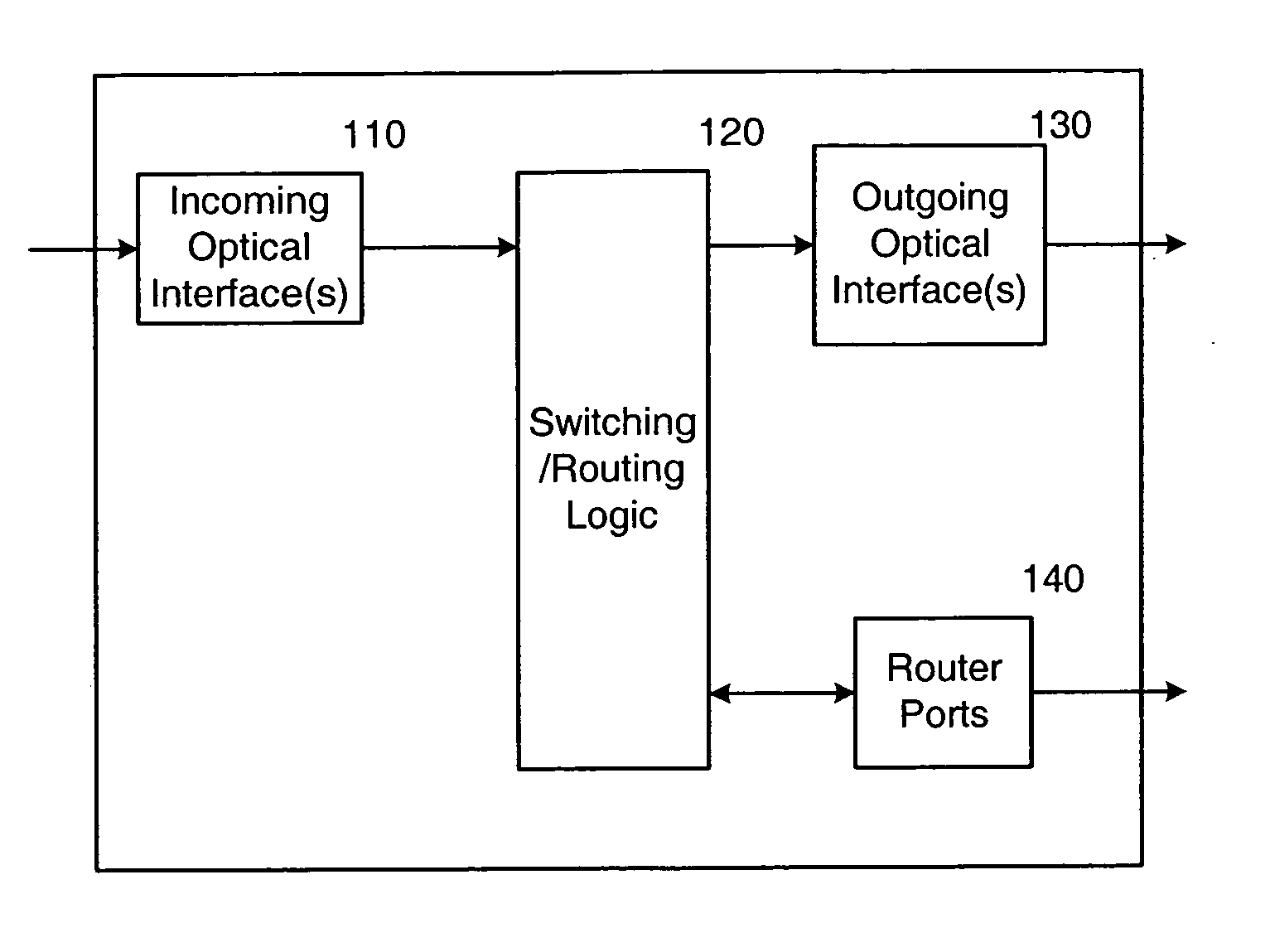
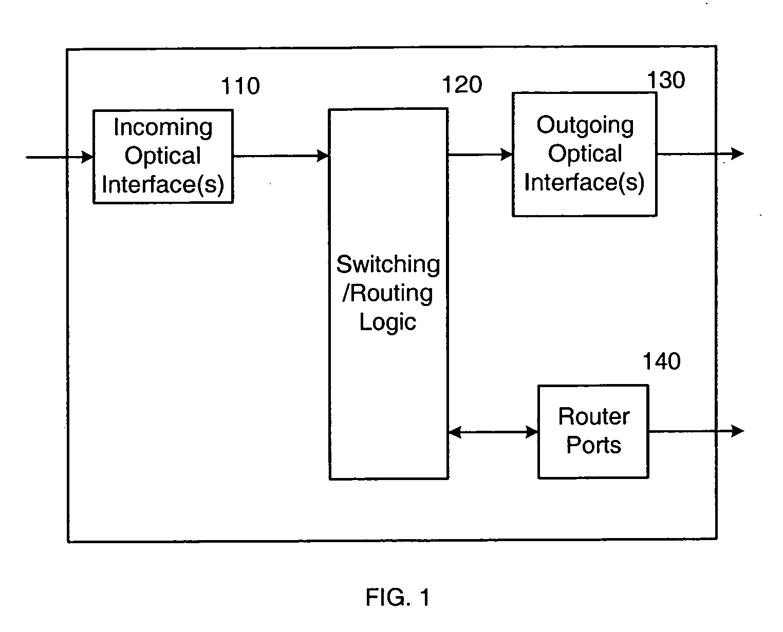
[0026] In an embodiment of the invention, an optical switch router performs both optical switching and traditional routing. The optical switch router includes optical interfaces for coupling to one or more incoming optical fibers and to one or more outgoing optical fibers, and also indudes a number of traditional router ports. Individual incoming optical data streams received over the incoming optical fiber(s) can be selectively passed through to one or more of the outgoing optical fibers or “dropped” from the optical communication path for traditional routing. Routed traffic, which can be received over the router ports or from the “dropped” optical data streams, can be forwarded over optical data streams that are “added” to the outgoing optical fiber(s). The “added” optical data streams may be added to the outgoing optical fiber(s) at any unused wavelengths, including, but not limited to, the wavelengths of the “dropped” optical data streams.

[0027]FIG. 1 shows a representation of ...


PUM


Abstract

An optical switch router performs both optical switching and traditional routing. The optical switch router includes optical interfaces for coupling to one or more incoming optical fibers and to one or more outgoing optical fibers, and also includes a number of traditional router ports. Individual incoming optical data streams received over the incoming optical fiber(s) can be selectively passed through to one or more of the outgoing optical fibers or “dropped” from the optical communication path for traditional routing. Routed traffic, which can be received over the router ports or from the “dropped” optical data streams, can be forwarded over optical data streams that are “added” to the outgoing optical fiber(s). The “added” optical data streams may be added to the outgoing optical fiber(s) at any unused wavelengths, including, but not limited to, the wavelengths of the “dropped” optical data streams.

Description

PRIORITY [0001] The present application claims priority from the following commonly-owned United States patent application, which is hereby incorporated herein by reference in its entirety: [0002] U.S. Provisional Patent Application No. 60 / 225,594 entitled OPTICAL INTERNET PROTOCOL SWITCH ROUTER, which was filed on Aug. 15, 2000 in the names of Bruce A. Schofield, James V. Luciani, and Michael J. Craren. CROSS-REFERENCE TO RELATED APPLICATION(S) [0003] The present application may be related to the following commonly-owned United States patent applications, which are hereby incorporated herein by reference in their entireties: [0004] U.S. patent application Ser. No. 09 / 740,705 entitled SYSTEM, DEVICE, AND METHOD FOR PRODUCING OPTICAL DATA STREAMS IN AN OPTICAL COMMUNICATION NETWORK, which was filed on Dec. 19, 2000 in the name of Bruce A. Schofield; [0005] U.S. patent application Ser. No. 09 / 740,706 entitled SYSTEM, DEVICE, AND METHOD FOR DROPPING AND ADDING OPTICAL DATA STREAMS IN A...

Claims


Application Information

Patent Timeline
Patent Type & Authority Applications(United States)
IPC IPC(8): H04J14/00H04J14/02H04Q11/00
CPCH04J14/0205H04J14/0206H04J14/021H04J14/0212H04L45/00H04L45/60H04Q2011/0073H04Q11/0005H04Q11/0066H04Q2011/0015H04Q2011/0016H04Q2011/0039H04Q2011/005H04L45/62
Inventor SCHOFIELD, BRUCE A.LUCIANI, JAMES V.CRAREN, MICHAEL J.
Owner NORTEL NETWORKS INC
Why Eureka
Try Eureka