Laminated structure with a filled viscoelastic layer and method

a viscoelastic layer and laminated structure technology, applied in the direction of synthetic resin layered products, ceramic layered products, transportation and packaging, etc., can solve the problems of painting quality, labor required for installation, non-recyclability,

Inactive Publication Date: 2007-02-01
MATERIAL SCIENCES CORPORATION
View PDF9 Cites 3 Cited by
  • Summary
  • Abstract
  • Description
  • Claims
  • Application Information

AI Technical Summary

Benefits of technology

[0010] The present invention provides a constrained layer viscoelastic laminate material suitable for vehicular body panels that meets the strength, noise and vibration, and packaging requirements of modern vehicles.

Problems solved by technology

Disadvantages of mastics include: build variations between vehicles due to manual placement; airborne paint contamination resulting in paint quality issues; labor required for installation; inconsistent melt characteristics; non recyclability; susceptibility to damage during installation; interior packaging limitations due to thickness of mastics; providing only localized damping; and assembly line space requirements.
Disadvantages of this configuration include the additional tooling required to manufacture the doubler, the welding operation required for attachment, interior packaging limitations due to thickness of the doubler, and localized damping only in the area of the doubler panel.
Disadvantages of spray-on deadeners include: masking requirement for spray applications; non-recyclability; process limited by overspray and dripping; robot requirement for application; paint shop contamination; labor and assembly line space requirement; on-going maintenance of robots; and only localized damping coverage.
Disadvantages of fiberglass matting include labor and assembly space requirements; fastener requirements; interior packaging limitations due to thickness; and the added expense and weight of the fiberglass parts.
However, these panels tend to be thicker than their respective solid metal designs due to the inclusion of the viscoelastic layer and the desire to maintain the stiffness of the panel.
This additional thickness may add weight, albeit less weight than the above mentioned treatments, as well as decrease the valuable packaging space in modern vehicles.

Method used


Image

  • Laminated structure with a filled viscoelastic layer and method
  • Laminated structure with a filled viscoelastic layer and method
  • Laminated structure with a filled viscoelastic layer and method

Examples


Embodiment Construction

[0020] The present invention provides a constrained layer viscoelastic laminate material suitable for vehicular body panels that meets the strength, noise and vibration, and packaging requirements of modern vehicles.

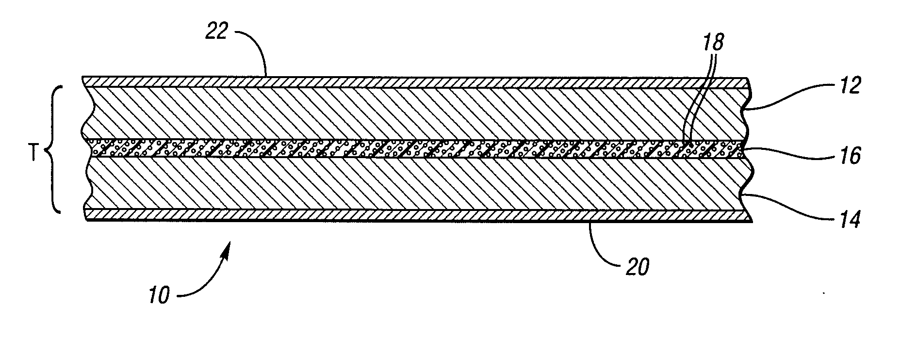
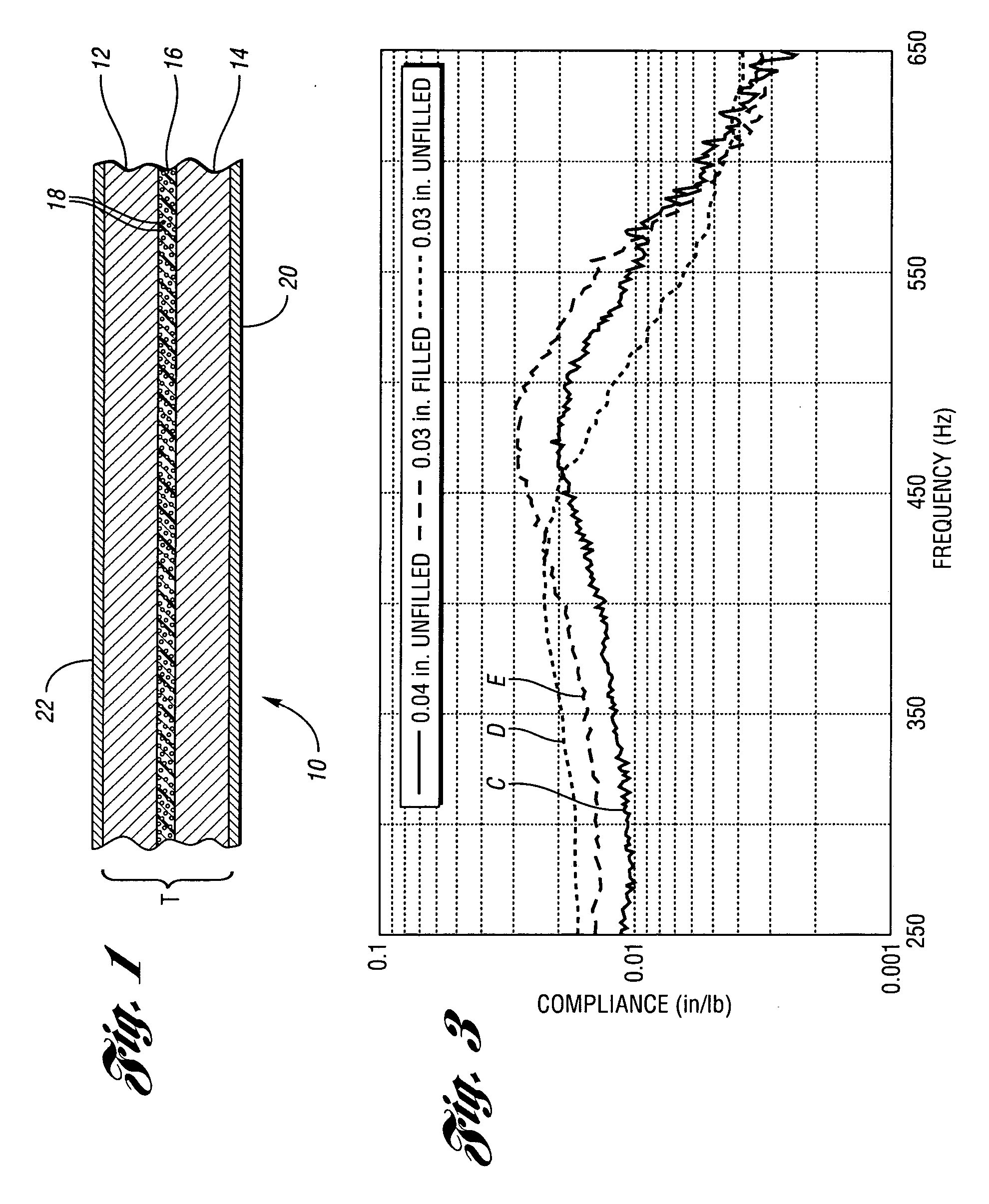
[0021] Specifically, the laminate of the present invention is formed from a laminated sheet structure (a.k.a. constrained layer viscoelastic material) 10 of thickness T, as illustrated schematically in FIG. 1. The laminated sheet structure 10 includes first and second constraining layers 12 and 14 having an engineered viscoelastic layer 16 therebetween spanning substantially the entirety of both constraining layers 12 and 14. The constraining layers 12 and 14 may be formed from any material with the necessary stiffness to provide support to the viscoelastic layer 16, such as plastics, aluminum, magnesium, titanium, and steel. In the preferred embodiment the material for the constraining layers 12 and 14 is steel. The constraining layers 12 and 14 may be the same thickne...


PUM

PropertyMeasurementUnit
particle sizeaaaaaaaaaa
thicknessaaaaaaaaaa
thicknessaaaaaaaaaa

Abstract

The present invention provides a panel providing improved noise and vibration attenuation. The panel is formed from a constrained layer viscoelastic laminate material having at least two constraining layers and at least one viscoelastic layer therebetween spanning the entirety of the constraining layers. Included within the viscoelastic layer is an effective amount of filler material operable to increase the static stiffness of the panel. A method of increasing the static stiffness of constrained layer viscoelastic materials is also provided.

Description

TECHNICAL FIELD [0001] The present invention relates to a laminated structure for sound and vibration reduction with a viscoelastic layer disposed between constraining layers, wherein the laminated structure has an increased static stiffness due to the presence of fillers within the viscoelastic layer. BACKGROUND OF THE INVENTION [0002] Laminated panels comprising a viscoelastic layer disposed between constraining layers have been used to attenuate noise and vibration in a number of different environments, especially to diminish the propagation of structural noise and the transmission of airborne noise. [0003] U.S. Pat. No. 6,202,462, to Hansen et al., issued Mar. 20, 2001 to the assignee of the present invention, and hereby incorporated by reference in its entirety, describes a method of making a vibration damping constrained layer viscoelastic laminate. [0004] Auto manufacturers have recently refocused efforts to reduce the noise of their vehicles both within the passenger cabin a...

Claims


Application Information

Patent Timeline
Patent Type & Authority Applications(United States)
IPC IPC(8): B32B15/04B32B27/20
CPCB32B5/04Y10T428/259B32B2250/03B32B2250/40B32B2255/205B32B2260/025B32B2307/544B32B2307/546B32B2605/00Y10T428/251Y10T428/25Y10T428/257Y10T428/256Y10T428/252B32B5/30Y10T428/249974Y10T428/31678
Inventor NASHIF, AHIDDENYS, ERIC
Owner MATERIAL SCIENCES CORPORATION
Why Eureka
Try Eureka