
Crusher

a crushing panel and sanding technology, applied in the field of crushing panels, can solve the problems of excessively large devices, prolonged crushing time, and difficult crushing at room temperature in such devices, and achieve the effects of reducing deformation, reducing pressure from crushing panels, and weakening the force applied to the material

Inactive Publication Date: 2007-02-08
SIGMA SEIKI
View PDF16 Cites 25 Cited by
  • Summary
  • Abstract
  • Description
  • Claims
  • Application Information

AI Technical Summary

Benefits of technology

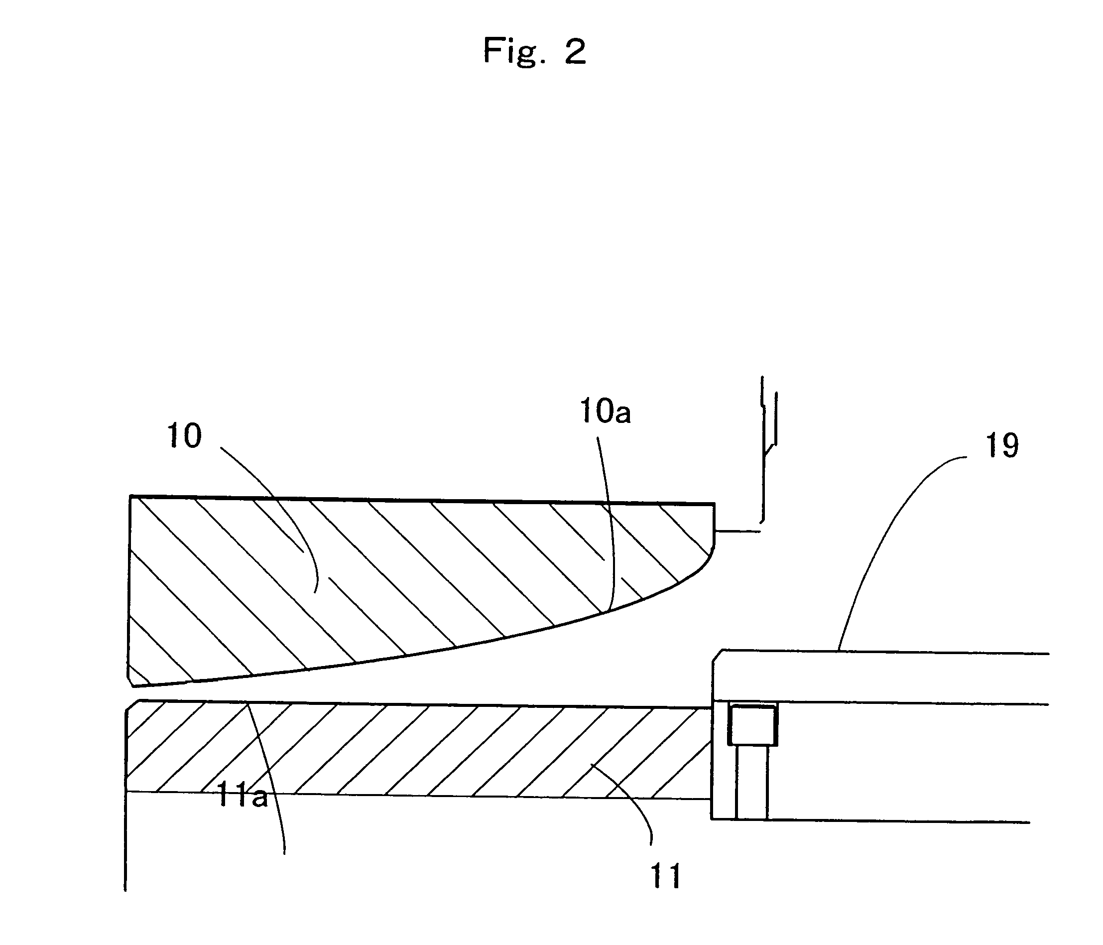
[0009] In order to solve the above-mentioned problems, the present invention provides, in claim 1, a crusher comprising a pair of crushing panels, each crushing panel having crushing blades on the face opposing the other crushing panel; a charging port for charging material to be crushed into a space where the crushing panels oppose each other, the charging port being formed near the center of one of the crushing panels; and a driving part for rotating at least one of the crushing panels; wherein the crushing blades are formed such that the material is crushed and pushed from the crushing panels by rotation of at least one of the crushing panels; and the angle formed by the pair of the crushing panels is smaller on the circumference side of the opposing faces of the crushing panels than on the central side of the opposing faces of the crushing panels. In such a crusher, when the material to be crushed has been crushed to a particular size, the pressure from the crushing panel is made less intense, thus weakening the force applied to the material and reducing deformation. In this manner, the crusher of the invention is capable of suitably crushing elastic materials.
[0010] In claim 2, the present invention provides such a crusher wherein the angle formed by the pair of the crushing panels is smaller on the circumference side of the opposing faces of the crushing panels than on the central side of the opposing faces of the crushing panels, in that, based on a concentric circular boundary formed on the opposing faces of the crushing panels, the above angle is smaller on the outer side of the boundary than on the inner side of the boundary. This crusher achieves the above-mentioned effects by forming the crushing blade-side surfaces of the crushing panels in a simple manner. That is, suitable crushing can be easily performed by merely adjusting the above-mentioned angle formed by the crushing panels according to conditions such as the characteristics of materials to be crushed, the desired size of crushed materials, crushing speed, etc.
[0012] On the outer side of the boundary, the opposing faces of the pair of the crushing panels may be substantially parallel to each other (claim 4). When the opposing faces of the pair of the crushing panels are parallel, elastic materials such as rubber materials can be properly crushed, minimizing deformation.
[0014] When the crushing blades are not sufficiently cooled by radiating heat from the external surfaces of the crushing panels through air, etc., the crushing blades can be effectively cooled in the above manner. This is effective in preventing the material to be crushed from becoming soft and easy to bend (easy to deform) due to an excess of frictional heat.

Problems solved by technology

However, crushing at room temperature is difficult in such devices.
Therefore, when a large amount of waste rubber materials are crushed for the recycling of rubber materials, there are problems such as excessively large-scale devices, prolonged crushing time, enormous amounts of labor and costs for the supply of liquid nitrogen, etc.
Furthermore, there is another disadvantage in that when the waste rubber materials are frozen, the physical properties thereof are changed and the uses thereof in recycling are limited.
However, when such a grinder is used to grind an elastic material to be ground such as a waste rubber material, the rubber powder obtained by grinding is relatively large (about 1.0-3.0 mm per side) and does not reach the size required for recycling as a rubber material (about 0.2-0.4 mm per side).
Furthermore, when such a grinder is used for grinding more finely, the rubber material to be ground cannot be suitably ground since the rubber material is deformed due to its own elasticity in the process of being ground, thus discharged without being ground.

Method used


Image

  • Crusher
  • Crusher
  • Crusher

Examples


first embodiment

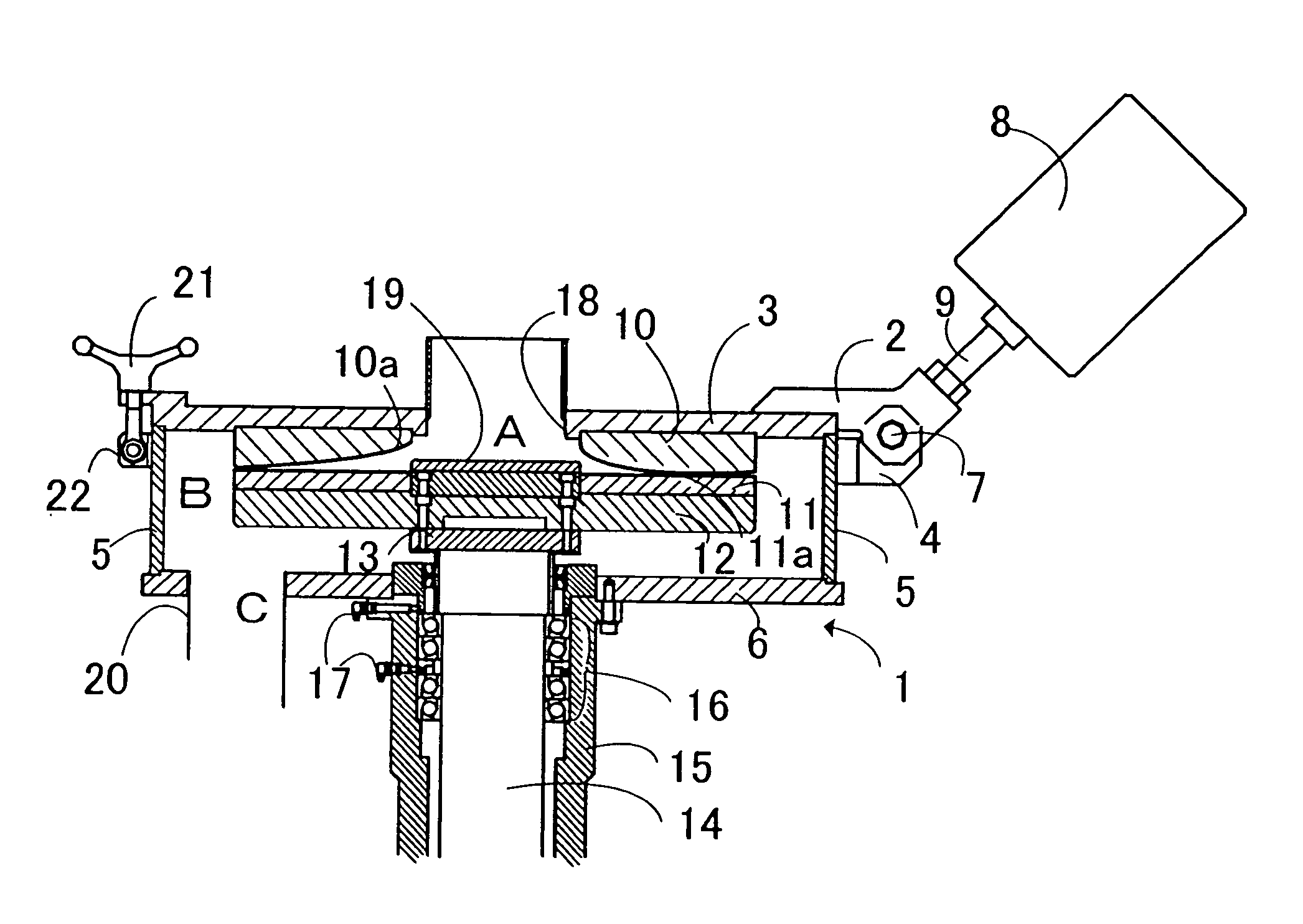
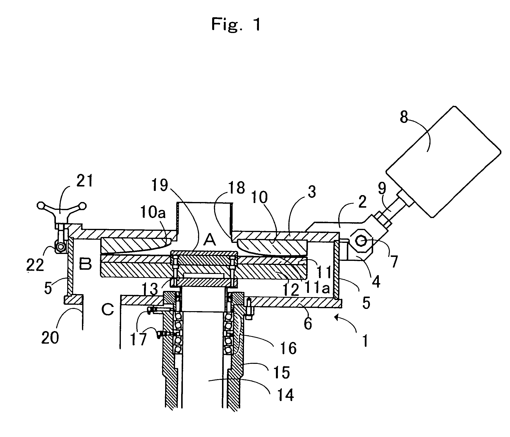
[0038] Preferable embodiments of the present invention are described below with reference to the drawings. FIGS. 1 and 2 show the present invention. The elements represented by the same symbols in the drawings have similar or the same structures, which provide similar or the same functions and effects.

[0039] In crusher body 1, upper cover 3, which is fixed to upper holder 2 by welding, bolting, or the like, and case 5 and lower cover 6, which are similarly fixed to lower holder 4, are structured so as to open and close freely by hinge 7. Upper holder 2 and lower holder 4 are connected to weight-adjusted balance weight 8 via handle 9 such that, when opened to a particular position, upper cover 3 does not close itself due to its own weight. Disk-shaped upper crushing panel 10 (diameter: about 500 mm) formed of materials such as carbon steel (for example, SKD-11), etc. is fixed to the lower side of the upper cover by means of bolts, etc. In this embodiment, upper crushing panel 10 has ...

second embodiment

[0052] In the second embodiment in FIG. 4, upper crushing panel 100 comprises first crushing blade face 100a, which is formed at a predetermined angle, and second crushing blade face 100b, which continues from first crushing blade face 100a at concentric circular boundary P and is formed at an angle different from the above predetermined angle.

[0053] Passage 23 for passing cooling water is provided within upper crushing panel 100. Passage 23 is preferably provided on the circumference side of crushing panel 100, where intense frictional heat is generated at the time of crushing. The cooling water supplied from water supply part 24, which is connected to passage 23, is circulated within crushing panel 100 to cool crushing panel 100 and crushing blade face 100a, and then discharged outside via water discharge part 25.

[0054] In FIG. 5, the passage for circulating cooling water is provided only in upper crushing panel 100, which is a fixed crushing panel. However, the present invention...

third embodiment

[0072] Furthermore, in the third embodiment, as shown in FIG. 12 (a plan view of an upper crushing panel, the rectangular blades not being shown for description) and FIG. 16, a group of three segments (for example, 100-1 to 100-3) is formed in a pattern such that the areas of the crushing blades having saw-toothed cross sections become gradually smaller in the direction of the circumference of upper crushing panel 100. The crushing blades formed in such a pattern enhance shearing capacity at the boundary between the crushing blades having saw-toothed cross sections and the crushing blades having rectangular cross sections, thus improving crushing efficiency.

[0073] FIGS. 13 to 15 show enlarged views of segments 100-1, 100-2, and 100-3 respectively, with (a) being a plan view, (b) being a side view seen in the direction of B, and (c) being an A-A enlarged sectional view. As shown in FIGS. 13 (b), 14 (b), and 15 (b), in each segment, the height of crushing blades having saw-toothed cro...


PUM


Abstract

The present invention provides a crusher that is capable of crushing material such as waste rubber material under the conditions of room temperature without causing heating due to excessive friction, etc. The crusher of the invention comprises a pair of crushing panels, each crushing panel having crushing blades on the face opposing the other crushing panel; a charging port for charging material to be crushed into a space where the crushing panels oppose each other, the charging port being formed near the center of one of the crushing panels; and a driving part for rotating at least one of the crushing panels; wherein the angle formed by the pair of the crushing panels is smaller on the circumference side of the opposing faces of the crushing panels than on the central side of the opposing faces of the crushing panels.

Description

TECHNICAL FIELD [0001] The present invention relates to a crusher, and particularly to a crusher that is suitable for crushing elastic and combustible materials such as waste rubber materials, typically waste tires of automobiles or the like. BACKGROUND ART [0002] In recent years, technologies have been developed to recycle waste rubber materials as new rubber products or to use them as fuels, wherein such waste rubber materials are, for example, waste tires or remnants resulting from the production processes of rubber products such as a shoe sole component punched out from rubber sheets. For example, rubber powders crushed to sizes below a particular level can be reused for rubber soles of shoes, beach sandals, tire extenders, parts of asphalt pavement materials, etc. In order to perform such reuses, it is necessary to crush waste rubber materials to extremely fine powders. For example, when used for the rubber soles of shoes, the rubber powder particle must be about 0.4 mm per sid...

Claims


Application Information

Patent Timeline
Patent Type & Authority Applications(United States)
IPC IPC(8): B02C7/04B02C7/08B02C7/12
CPCB02C7/08B02C2201/04B02C7/12
Inventor SANAGI, HARUOOCHIAI, AKIHIROMURATA, TSUTOMU
Owner SIGMA SEIKI
Learn More