Electric parking brake system

a technology of parking brakes and brakes, which is applied in the direction of brake cylinders, anti-theft devices, braking systems, etc., can solve the problems of complex structure of parking brake systems, low actual braking force, and malfunction of inclination sensors, so as to improve the reliability of electric parking brake systems

Active Publication Date: 2007-02-08
SUBARU CORP
View PDF4 Cites 32 Cited by
  • Summary
  • Abstract
  • Description
  • Claims
  • Application Information

AI Technical Summary

Benefits of technology

[0025] The present inventions as mentioned above have the following effect for attaining the second purpose. That is, according to the fourth to sixth aspects of the present invention, even if one of vehicle condition detecting sensors such as inclination sensors provided in the electric parking brake system is

Problems solved by technology

However, there may occur a malfunction of inclination sensor in such a case.
In other words, the electric parking brake system requires cooperation with an engine control system for controlling the engine r. p. m. etc., but for doing so, a structure of the parking brake system becomes complicated.
Furthermore, as the electric parking brake has, f

Method used


Image

  • Electric parking brake system
  • Electric parking brake system
  • Electric parking brake system

Examples


first embodiment

[First Embodiment]

[0037] An electric parking brake system as a first embodiment of the present invention will be hereinafter explained with FIGS. 1-3.

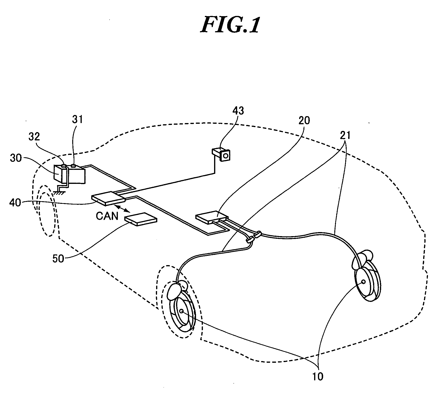
[0038] As shown in FIG. 1, an electric parking brake system comprises a parking brake 10, an actuator unit 20, a battery 30, a controller 40 and a vehicle side unit 50.

[0039] The parking brake 10 is a brake apparatus for preventing a movement of a vehicle while stopping or parking through braking vehicle wheels, and provided at respective wheel hub portions of rear left and right wheels. The parking brake 10 comprises a brake drum (not shown) provided at an inner diameter side of a rotor of a disc brake and a brake shoe (not shown) contacting with the inner diameter side of the brake drum by a pressure while applying a braking force.

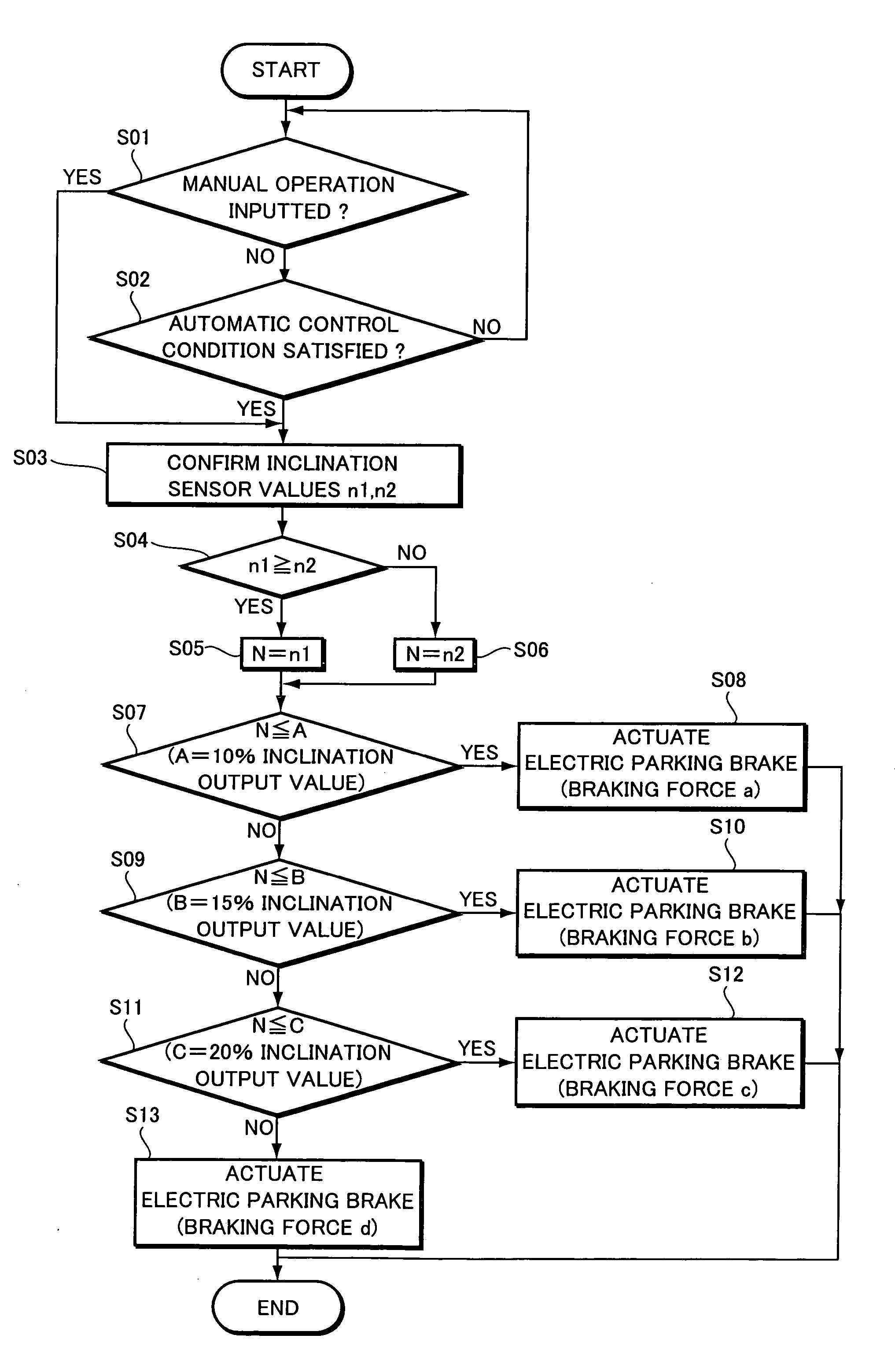
[0040] The actuator unit 20 actuates the brake shoe of the parking brake 10 to make the changeover between a braking condition where the braking force is applied and a brake released condition where the ...

second embodiment

[Second Embodiment]

[0080] Next, a second embodiment of the present invention will be explained with reference to FIGS. 4-6. The explanation about the same parts as those of the first embodiment is omitted, and the explanation about different points therefrom is mainly given.

[0081]FIG. 4 is the schematic view of the electric parking brake system as the second embodiment, and FIG. 5 is the block diagram showing a circuit structure of the electric parking brake system.

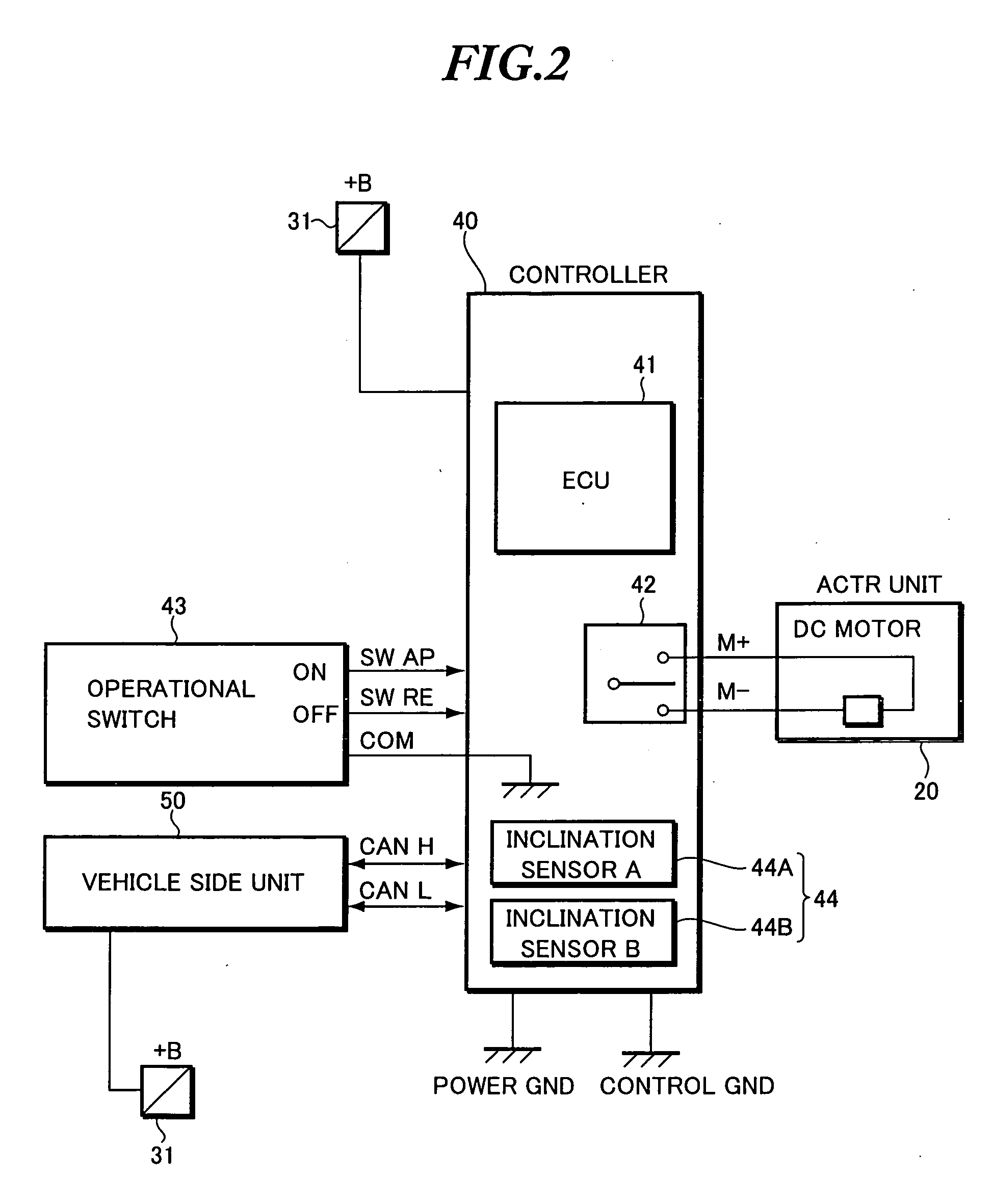
[0082] The circuit structure of the electric parking brake system of the second embodiment is different from that of the first embodiment about the following two points. One is that a single inclination sensor 44 is provided in the controller 40, and another is that the output of a fluid pressure sensor 51 connected to a VDC control unit of the vehicle side unit 50 is transmitted to the ECU 41 of the controller 40.

[0083] The fluid pressure sensor 51 works as vehicle condition detecting means, and detects a brake fluid ...


PUM


Abstract

An electric parking brake system is equipped with a parking brake driven by an electric actuator for braking wheels of a vehicle, a vehicle condition sensing section for detecting vehicle conditions, a target braking force setting section for setting a target braking force on the basis of vehicle condition detected, compared and weighted by the vehicle condition sensing section so as to overcome a trouble of a part of sensing section, a parking condition detecting section for sensing a change of the vehicle condition from a stopping condition to a parking condition, and a control section for increasing a braking force according to the change in the vehicle condition so as to avoid a creep movement of the vehicle. Thereby, the electric parking brake system with a highly improved reliability can be provided.

Description

BACKGROUND OF THE INVENTION [0001] 1. Field of the Invention [0002] The present invention relates to an electric parking brake system provided on such a vehicle as an automotive vehicle. [0003] The present application claims priority from Japanese Patent Application Nos. 2005-229692 and 2005-266612, the disclosures of which are incorporated herein by reference. [0004] 2. Description of the Related Art [0005] The electric parking brake system is usually actuated by such an electric actuator as an electric motor for applying a braking force to a wheel of a vehicle while the vehicle is parking or stopping (see, for example, Japanese patent application laid-open No. 2004-51039). [0006] As the electric parking brake is easily operational through an electrical changeover switch operated by a driver, such troublesome works as operations by a manual lever or foot stepping down operations of a brake pedal can be reduced. And, unintentional vehicle creeps due to a creeping phenomenon in an au...

Claims


Application Information

Patent Timeline
IPC IPC(8): B60T8/32
CPCB60T13/74B60T7/22
Inventor MAKISHIMA, TAKAHARUUCHIMURA, YUKIYAICHIKAWA, KATSUFUMI
Owner SUBARU CORP
Why Eureka
Try Eureka