Probe station thermal chuck with shielding for capacitive current

a capacitive current and thermal chuck technology, applied in the field of probe stations, can solve the problems of low electrical noise, common noise source, and high noise level

Inactive Publication Date: 2007-02-08
FORMFACTOR BEAVERTON INC
View PDF99 Cites 84 Cited by
  • Summary
  • Abstract
  • Description
  • Claims
  • Application Information

AI Technical Summary

Problems solved by technology

When making the low voltage and low current measurements common to testing integrated circuit devices, even very low levels of electrical noise are unsatisfactory.
Thermal chucks include several sources of noise and unacceptably high levels of noise are a common problem when using a thermal chuck.
One known source of noise is the result of expansion or contraction of the components of the thermal chuck due to changing temperature.
Expansion or contraction due to temperature change can also cause relative transverse movement between the multiple material layers of the chuck.
In a probe station chuck, the triboelectric current can appear as noise in the test measurements.
The operation of the thermal units by the thermal driver controller is another potential source of noise when using a thermal chuck.
This results in a displacement of charges in the dielectric material surrounding the conductors which manifests itself as a displacement or capacitive current coupled to the conductive top surface of the chuck.
This capacitive current appears as noise in the test measurements.
However, the shielding layers of conductive material in the chuck have proven unsuccessful in eliminating the noise from the thermal driver.

Method used


Image

  • Probe station thermal chuck with shielding for capacitive current
  • Probe station thermal chuck with shielding for capacitive current
  • Probe station thermal chuck with shielding for capacitive current

Examples


Embodiment Construction

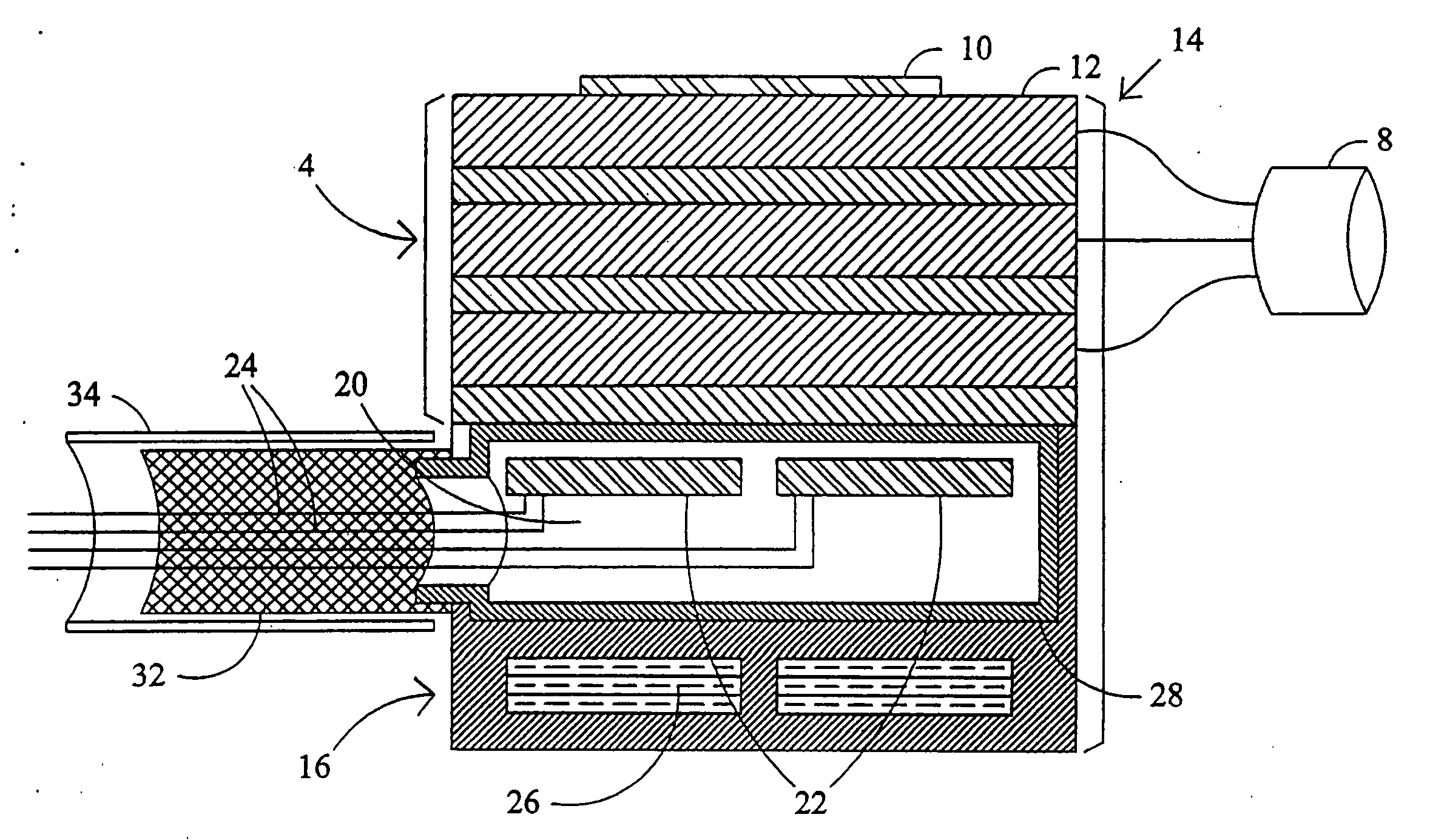
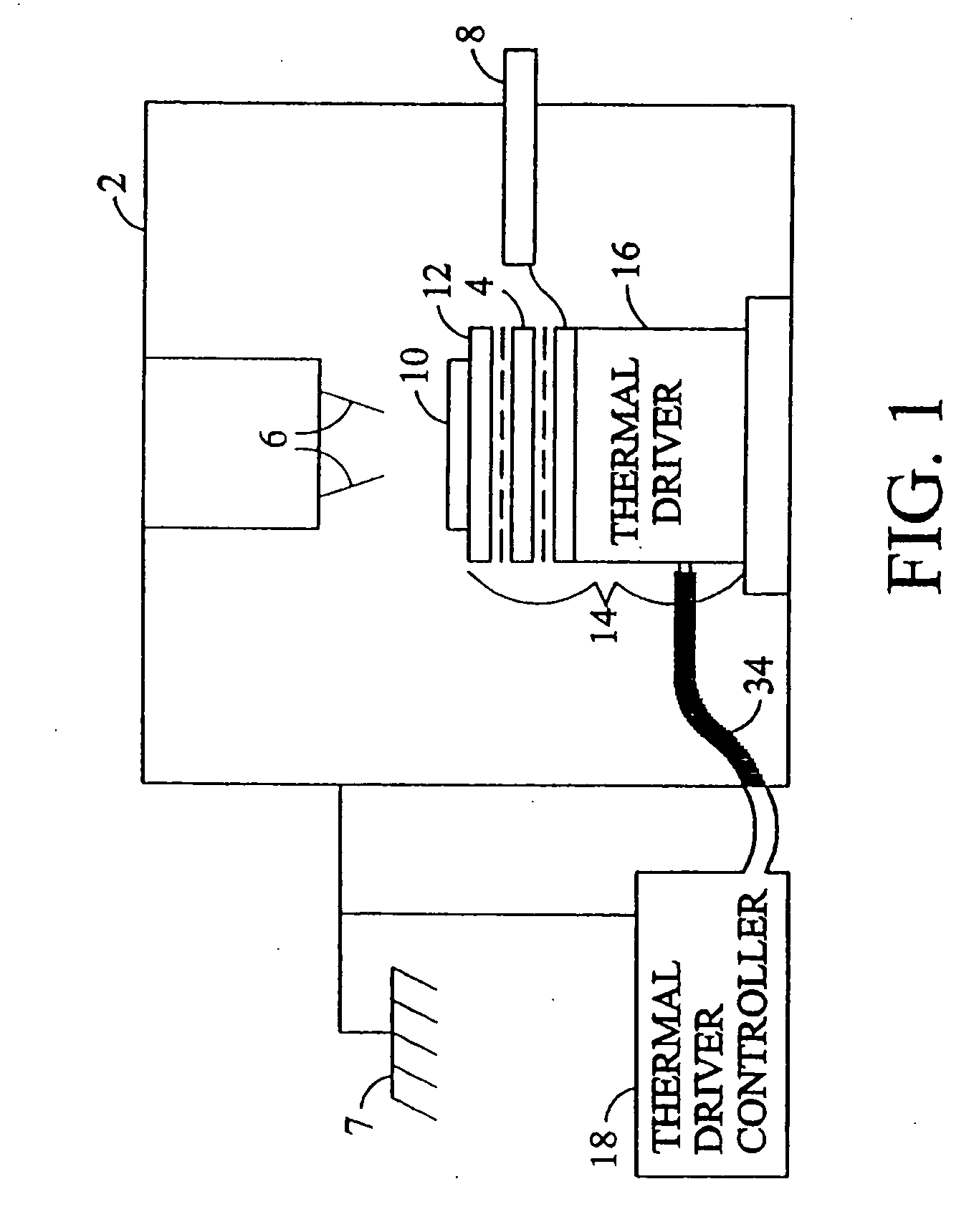
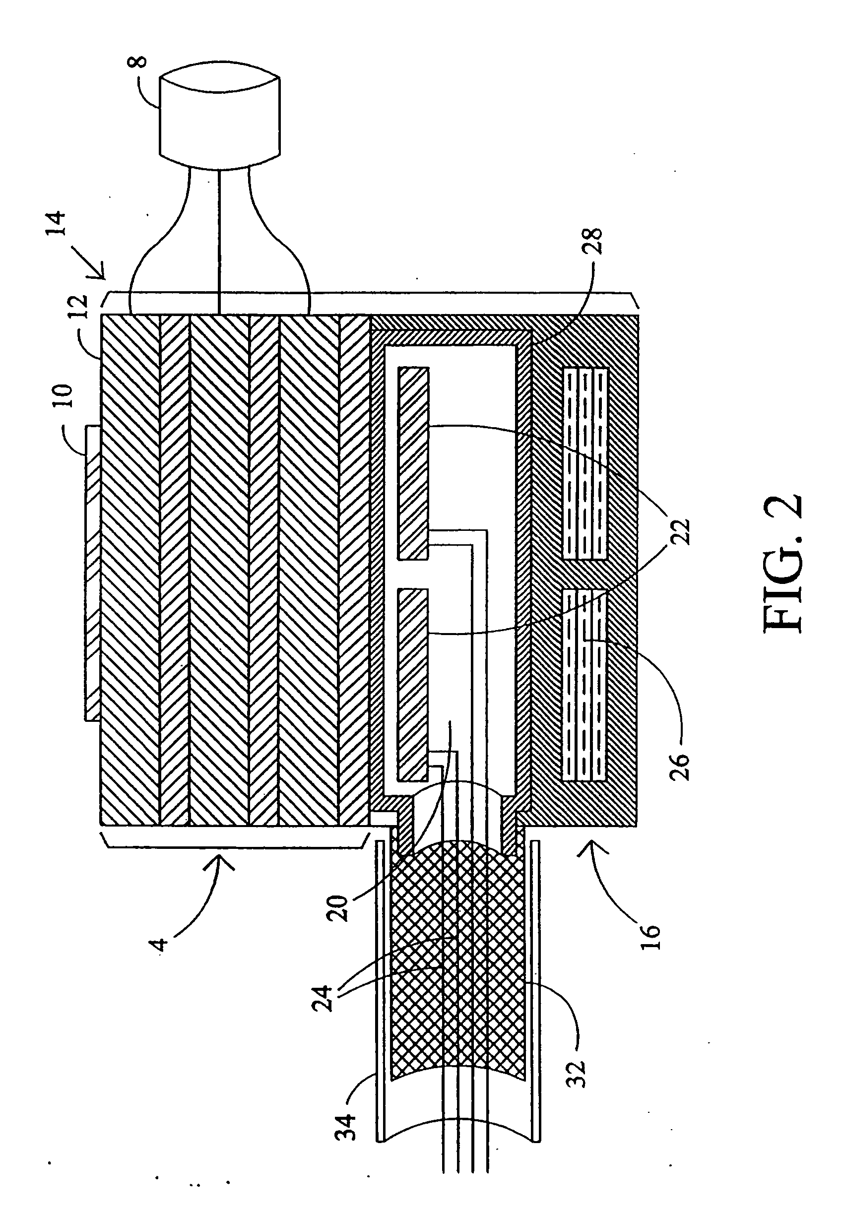
[0014] As illustrated in FIG. 1, a probe station generally includes an environmental enclosure 2 in which is located a chuck 4 and one or more probes 6. The environmental enclosure 2 is typically constructed of a conductive material and grounded 7 so that the chamber, interior to the enclosure 2, is shielded from electromagnetic fields emanating from outside of the enclosure 2. The chuck 4 typically comprises multiple layers of conductive and dielectric materials that are connected to the various conductors of a coaxial or triaxial cable 8. The chuck 4 includes a securement technique for securing a device under test 10, generally a wafer of semiconductor material, to the upper surface 12 of the chuck 4. The upper surface 12 of the chuck 4 is typically conductive. One technique for securing a device under test 10 relies on a vacuum source (not shown) located outside of the environmental enclosure. The vacuum source communicates through appropriate control valves and piping with apert...


PUM


Abstract

To reduce noise in measurements obtained by probing a device supported on surface of a thermal chuck in a probe station, a conductive member is arranged to intercept current coupling the thermal unit of the chuck to the surface supporting the device. The conductive member is capacitively coupled to the thermal unit but free of direct electrical connection thereto.

Description

CROSS REFERENCE TO RELATED APPLICATIONS [0001] This is a continuation of application Ser. No. 10 / 626,903, filed Jul. 25, 2003; which is a continuation of application Ser. No. 10 / 308,847, filed Dec. 2, 2002, now U.S. Pat. No. 6,642,732 B2, issued Nov. 4, 2003; which is a continuation of application Ser. No. 10 / 179,771, filed Jun. 24, 2002, now U.S. Pat. No. 6,512,391 B2, issued Jan. 28, 2003; which is a continuation of application Ser. No. 09 / 345,571, filed Jun. 30, 1999, now U.S. Pat. No. 6,445,202, issued Sep. 3, 2002.BACKGROUND OF THE INVENTION [0002] The present invention is directed to probe stations suitable for making low current and low voltage measurements and, more particularly, to a system for reducing noise due to capacitive currents resulting from the operation of a thermal chuck for a probe station. [0003] Integrated circuit devices are typically manufactured in and on a wafer of semiconductor material using well-known techniques. Prior to cutting the individual integra...

Claims


Application Information

Patent Timeline
Patent Type & Authority Applications(United States)
IPC IPC(8): G01R31/02G01R1/06G01R1/18G01R31/26G01R31/28H01L21/66H01L35/00H01L35/32
CPCG01R1/18G01R31/2855G01R31/2862H01L35/32G01R31/2874G01R31/2879H01L35/00G01R31/2865H10N10/00H10N10/17H01L22/00
Inventor COWAN, CLARENCE E.TERVO, PAUL A.DUNKLEE, JOHN L.
Owner FORMFACTOR BEAVERTON INC
Why Eureka
Try Eureka