Display device, method, and terminal device having switchable viewing angle
- Summary
- Abstract
- Description
- Claims
- Application Information
AI Technical Summary
Benefits of technology
Problems solved by technology
Method used
Image

Examples
second embodiment
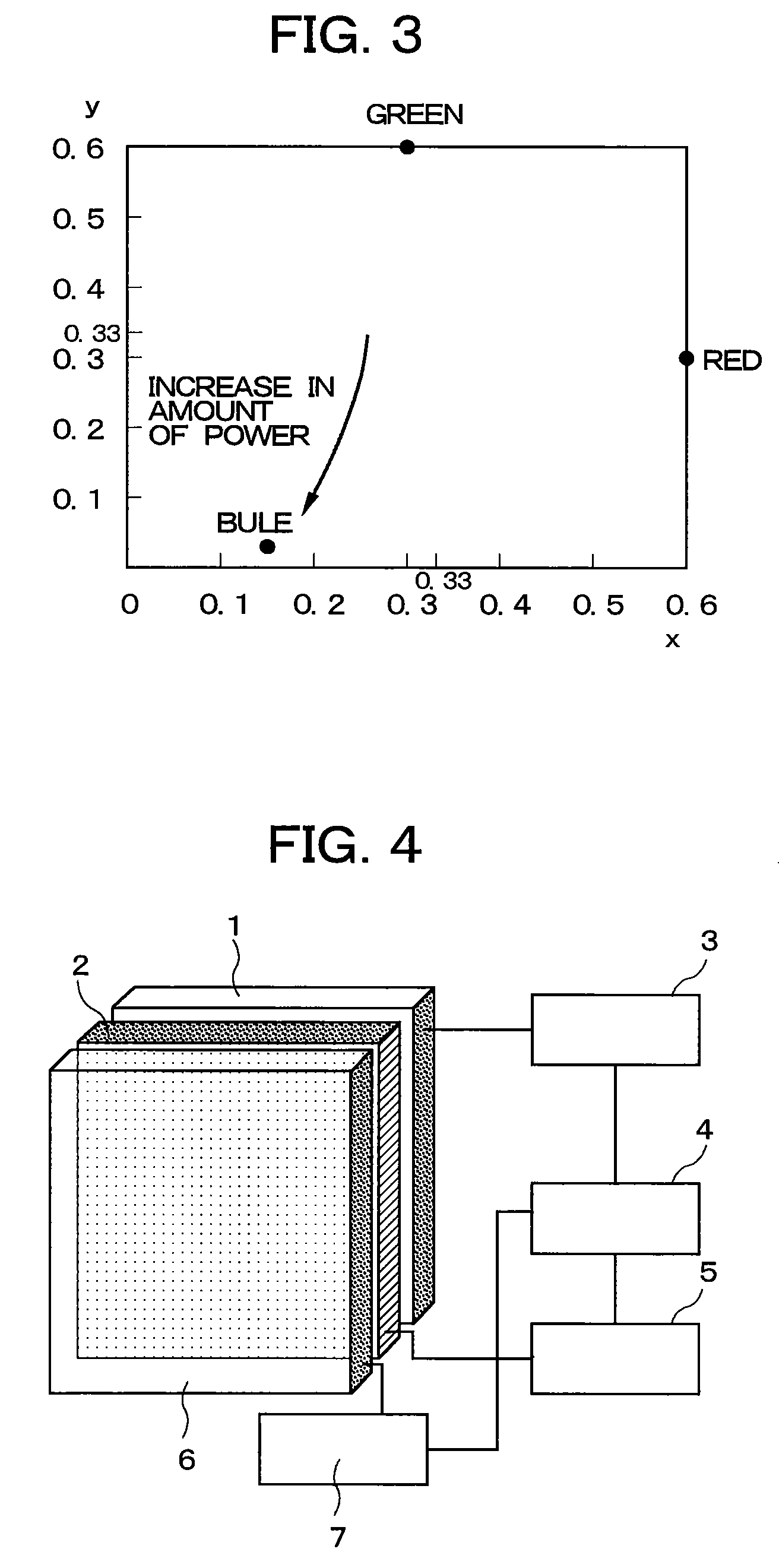
[0049] the present invention will next be described with reference to FIG. 4. The present embodiment differs from the embodiment shown in FIG. 1 in that the liquid crystal display panel 2 is disposed on the planar light source 1, and the switching element 6 is disposed on the liquid crystal display panel 2. The structure of the planar light source 1, the liquid crystal display panel 2, and the switching element 6 is the same as in the embodiment shown in FIG. 1. The structure of the control unit 4, the light source control unit 3, the display control unit 5, and the switching element control unit 7 is also the same as in the embodiment shown in FIG. 1.
first embodiment
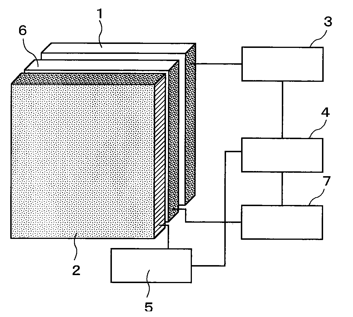
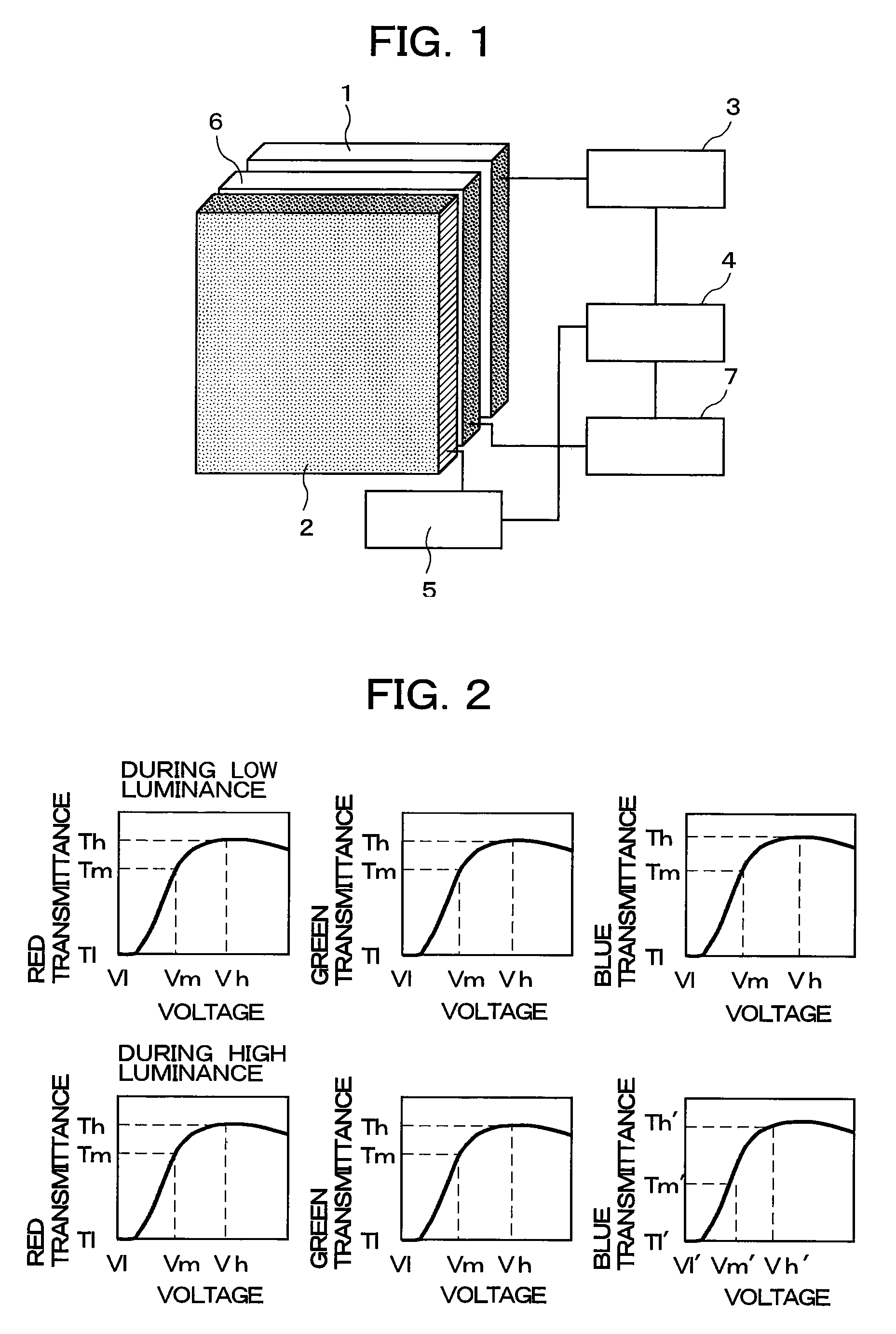
[0050] In the present embodiment, the control unit 4 controls the switching element 6 by means of the switching element control unit 7, and the luminance of the image displayed by the liquid crystal display device is prevented from varying during switching between a wide viewing angle and a narrow viewing angle by controlling the planar light source 1 through the light source control unit 3 so as to vary the luminance of the planar light source 1. The blue emission ratio of the planar light source 1 is prevented from increasing and changing the hue when the luminance is high, and the wavelength distribution is prevented from varying according to the transparent or scattering state of the switching element 6. This is achieved by resetting the contrast-setting voltage of the liquid crystal display panel 2. The present embodiment thereby demonstrates the same effects as the
third embodiment
[0051] the present invention will next be described. FIG. 5 shows the liquid crystal display device having a switchable viewing angle according to the present embodiment, and FIG. 6 is a sectional view showing the structure of the same. In the present embodiment, a linear louver 11 is disposed on the planar light source 1, the switching element 6 is disposed on the linear louver 11, and the display panel 2 is furthermore disposed on the switching element 6. The luminance of the planar light source 1 is controlled by the light source control unit 3, and the switching element control unit 7 controls the scattering state, transparent state, or other state of the switching element 6 to obtain a wide viewing angle or a narrow viewing angle. The transmittance of each color in the liquid crystal display panel 2 is controlled by the display control unit 5. The control unit 4 controls the light source control unit 3, the switching element control unit 7, and the display control unit 5.
[0052]...
PUM
 Abstract
Description
Claims
Application Information
 - R&D
- Intellectual Property
- Life Sciences
- Materials
- Tech Scout
- Unparalleled Data Quality
- Higher Quality Content
- 60% Fewer Hallucinations
Browse by: Latest US Patents, China's latest patents, Technical Efficacy Thesaurus, Application Domain, Technology Topic, Popular Technical Reports.
© 2025 PatSnap. All rights reserved.Legal|Privacy policy|Modern Slavery Act Transparency Statement|Sitemap|About US| Contact US: help@patsnap.com