Low spring constant, pneumatic suspension with vacuum chamber, air bearing, active force compensation, and sectioned vacuum chambers

a technology of low spring constant and vacuum chamber, which is applied in the direction of machine supports, instruments, printing, etc., can solve the problems of deterioration of temperature characteristics, heavy mechanism portion, and higher manufacturing cos

Inactive Publication Date: 2007-02-08
NIKON CORP
View PDF16 Cites 20 Cited by
  • Summary
  • Abstract
  • Description
  • Claims
  • Application Information

AI Technical Summary

Benefits of technology

[0009] Embodiments of the present invention are directed to an apparatus for providing a low spring constant, pneumatic suspension using vacuum for a projection system. The use of a vacuum chamber with either an air bearing or a low stiffness vacuum seal produces a low spring constant suspension mechanism for supporting...

Problems solved by technology

In general, an exposure apparatus having a mechanism portion with high rigidity, while providing a high apparatus performance capability, tends to have a heavy mechanism portion, and a higher manufacturing cost.
For example, in a mechanism portion, when members with high rigidity are coupled to each other through members having high rigidity, vibration can be easily transmitted, a bi-metal effect is generated at the time of temperature change (if different materials are used for the members), and the temperature characteristics may be deteriorated.
As a result of increasing rigidity of the mechanism portion, however, when the weight of the mechanism portion increases, there is also a possibility of increased construction cost of the device manufacturing factory in which the exposure apparatus is installed in order to deal with the weight of the exposure apparatus.
Among conventional technology with respect to a method of usi...

Method used


Image

  • Low spring constant, pneumatic suspension with vacuum chamber, air bearing, active force compensation, and sectioned vacuum chambers
  • Low spring constant, pneumatic suspension with vacuum chamber, air bearing, active force compensation, and sectioned vacuum chambers
  • Low spring constant, pneumatic suspension with vacuum chamber, air bearing, active force compensation, and sectioned vacuum chambers

Examples


Embodiment Construction

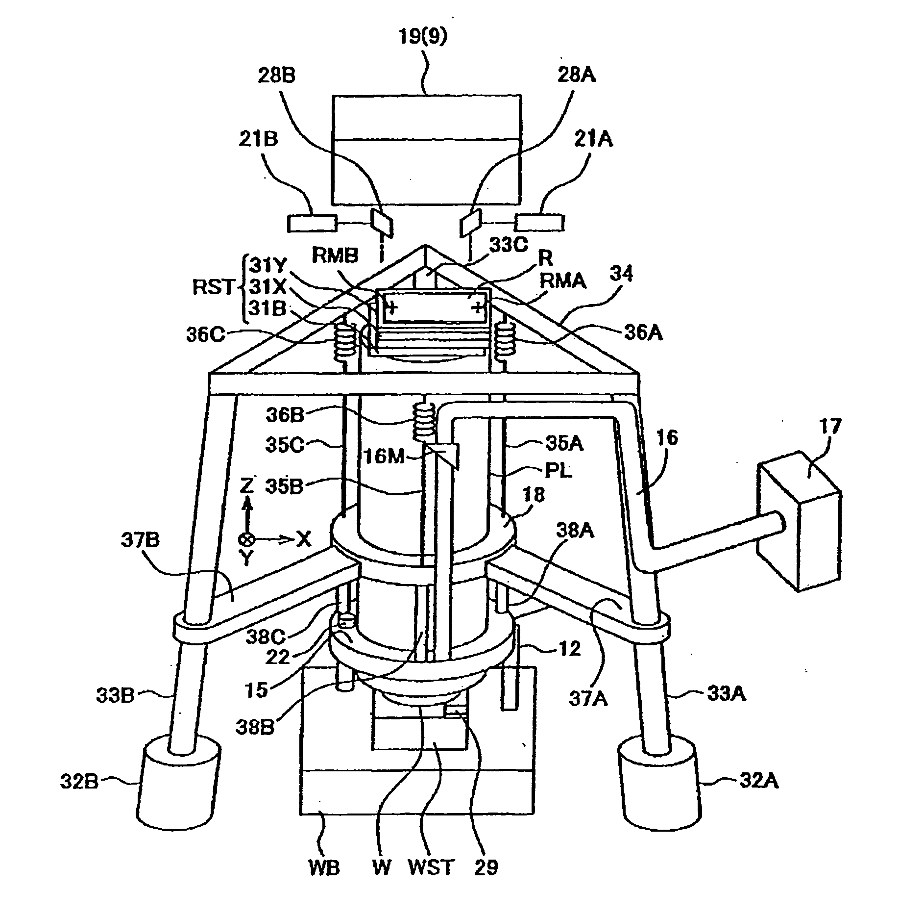
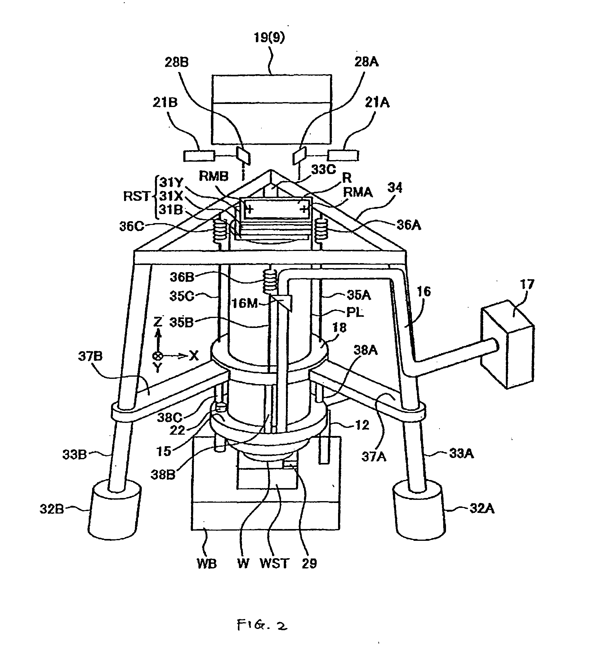
[0028] Embodiments of the present invention are directed to an apparatus for providing a low spring constant, pneumatic suspension using vacuum for the lens in a projection system. The projection system may be a batch type projection exposure apparatus such as a stepper or the like, or a scanning type projection exposure apparatus such as a scanning stepper or the like.

Projection Exposure Apparatus

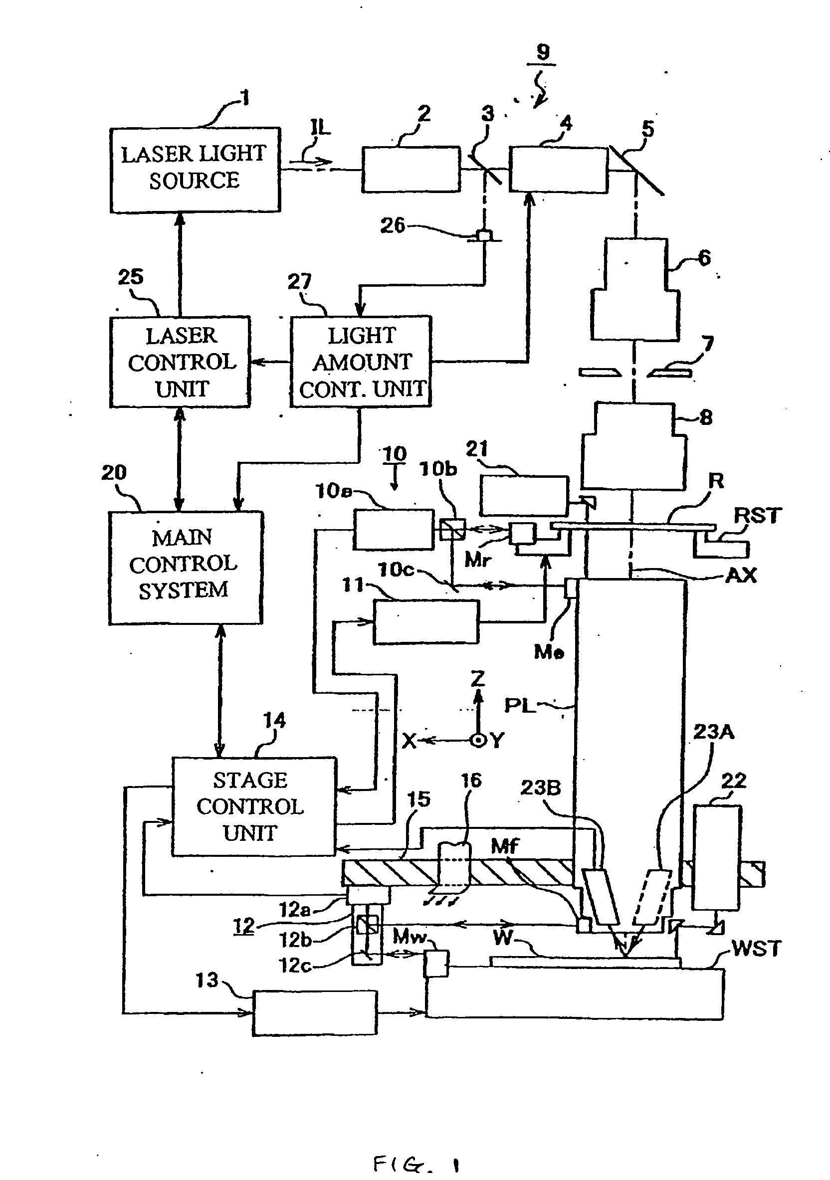
[0029]FIGS. 1-6 illustrate a projection exposure apparatus which may implement the low spring constant, pneumatic suspension mechanism of the present invention. FIG. 1 is a block diagram of different functional units which constitute the projection exposure apparatus of this embodiment. In FIG. 1, a chamber in which the projection exposure apparatus is located, is omitted. In FIG. 1, a laser light source 1 is provided. The laser light source 1 can be a KrF excimer laser (wavelength 248 nm) or an ArF excimer laser (wavelength 193 nm), for example. The light source also may be a device wh...


PUM


Abstract

Embodiments of the present invention are directed to an apparatus for providing a low spring constant, pneumatic suspension using vacuum for the lens in a projection system. In one embodiment, a pneumatic suspension system for a load comprises a frame; and a body movably disposed in the frame and spaced from a side wall of the frame by a gap to define a chamber in the frame above the body, the body being configured to be connected to the load. The frame includes an outlet to draw a gas from the chamber to lower the pressure in the chamber with respect to an ambient pressure outside the frame. An air bearing is formed in the gap between the body and the side wall of the frame to provide non-contact between the body and the frame. The pressure in the chamber is sufficiently lower than the ambient pressure to produce a lift force to lift the body and the load connected thereto with respect to the frame.

Description

CROSS-REFERENCES TO RELATED APPLICATIONS [0001] This application relates to co-pending, commonly assigned, U.S. patent application Ser. No. 11 / ______ (Ref. No. PA0 683), filed ______, entitled “Projection Optical Device and Exposure Apparatus,” which claims the benefit of U.S. Provisional Patent Application No. 60 / 614,426, filed Sep. 30, 2004, the entire disclosures of which are incorporated herein by reference.BACKGROUND OF THE INVENTION [0002] The present invention relates generally to a projection optical device provided with a projection optical system which projects an image of a predetermined pattern, and to an exposure apparatus which is used to transfer a pattern of a mask onto a substrate to manufacture various devices such as a semiconductor device, a liquid crystal display, and the like. [0003] In a lithography process, which is one process for manufacturing a semiconductor device, an exposure apparatus is used to transfer and expose a pattern formed on a reticle (or a ph...

Claims


Application Information

Patent Timeline
IPC IPC(8): F16M1/00G03B27/00
CPCG02B7/005
Inventor YUAN, BAUSANLEE, MARTIN E.PHILLIPS, ALTON H.CHANG, PING-WEIEBIHARA, AKIMITSU
Owner NIKON CORP
Why Eureka
Try Eureka