Developing treatment apparatus and developing treatment method

a technology of developing treatment apparatus and developing treatment method, which is applied in the direction of photomechanical apparatus, instruments, photosensitive materials, etc., can solve the problems of increased running cost, large space required, and large developing treatment apparatus, so as to reduce the size of the mesh plate and improve the yield

Inactive Publication Date: 2007-02-08
TOKYO ELECTRON LTD
View PDF15 Cites 4 Cited by
  • Summary
  • Abstract
  • Description
  • Claims
  • Application Information

AI Technical Summary

Benefits of technology

[0017] According to the present invention, since at least the surface of the mesh plate on the substrate side has been subjected to hydrophilic treatment, even if the developing solution is supplied from the developing solution supply nozzle onto the substrate through the mesh plate while the developing solution supply nozzle and the substrate are moving relative to each other so that the developing solution is held between the mesh plate and the substrate, the shear resistance works between the developing solution on the sub...

Problems solved by technology

Therefore, a large space is required for the motor, leading to a larger developing treatment apparatus.
Further, a large power consumption is required for rotation of the motor, resulting in increased running cost.
In the case of the developing treatment apparatus in which the wafer is carried by the roller-type carriage and developed, however, the rollers come into contact with the lower surface of the wafer contaminated with, for example, the developing solution.
Therefore, the rollers are contaminated, and the contaminant adheres to other portions of the wafer or to other wafers and accordingly diffuses, thus spreading the particle source.
This causes a large amount of particles and contaminates the wafer, for example, before it is developed, resulting i...

Method used


Image

  • Developing treatment apparatus and developing treatment method
  • Developing treatment apparatus and developing treatment method
  • Developing treatment apparatus and developing treatment method

Examples


Embodiment Construction

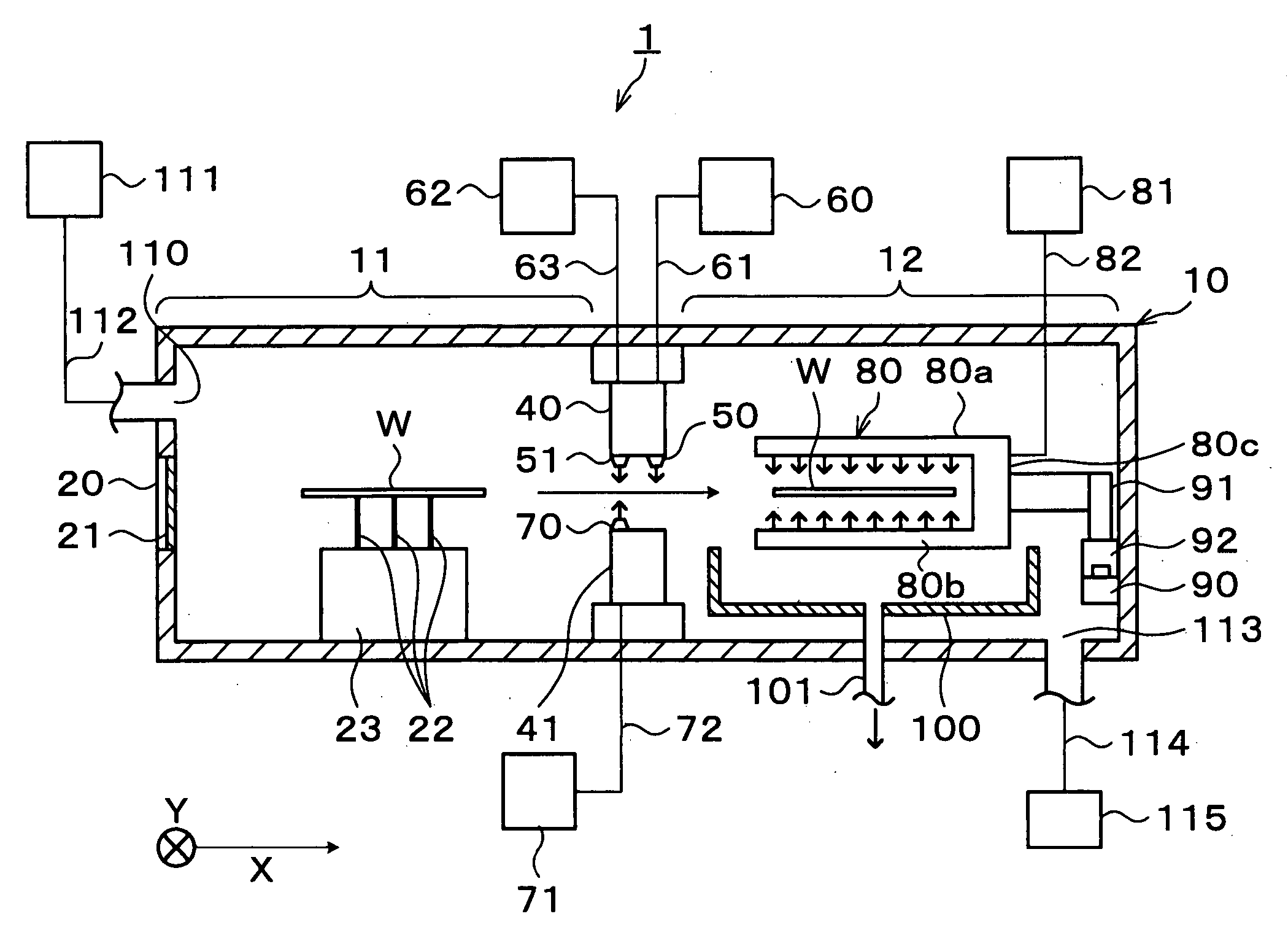
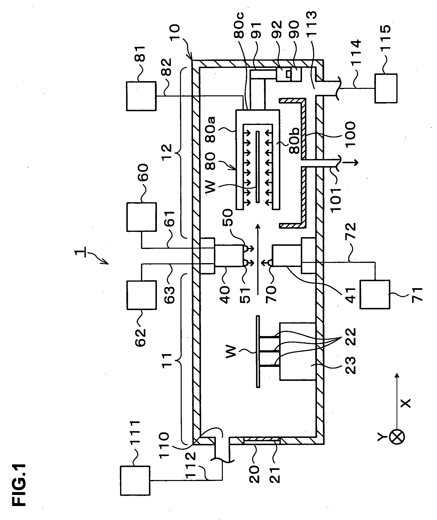
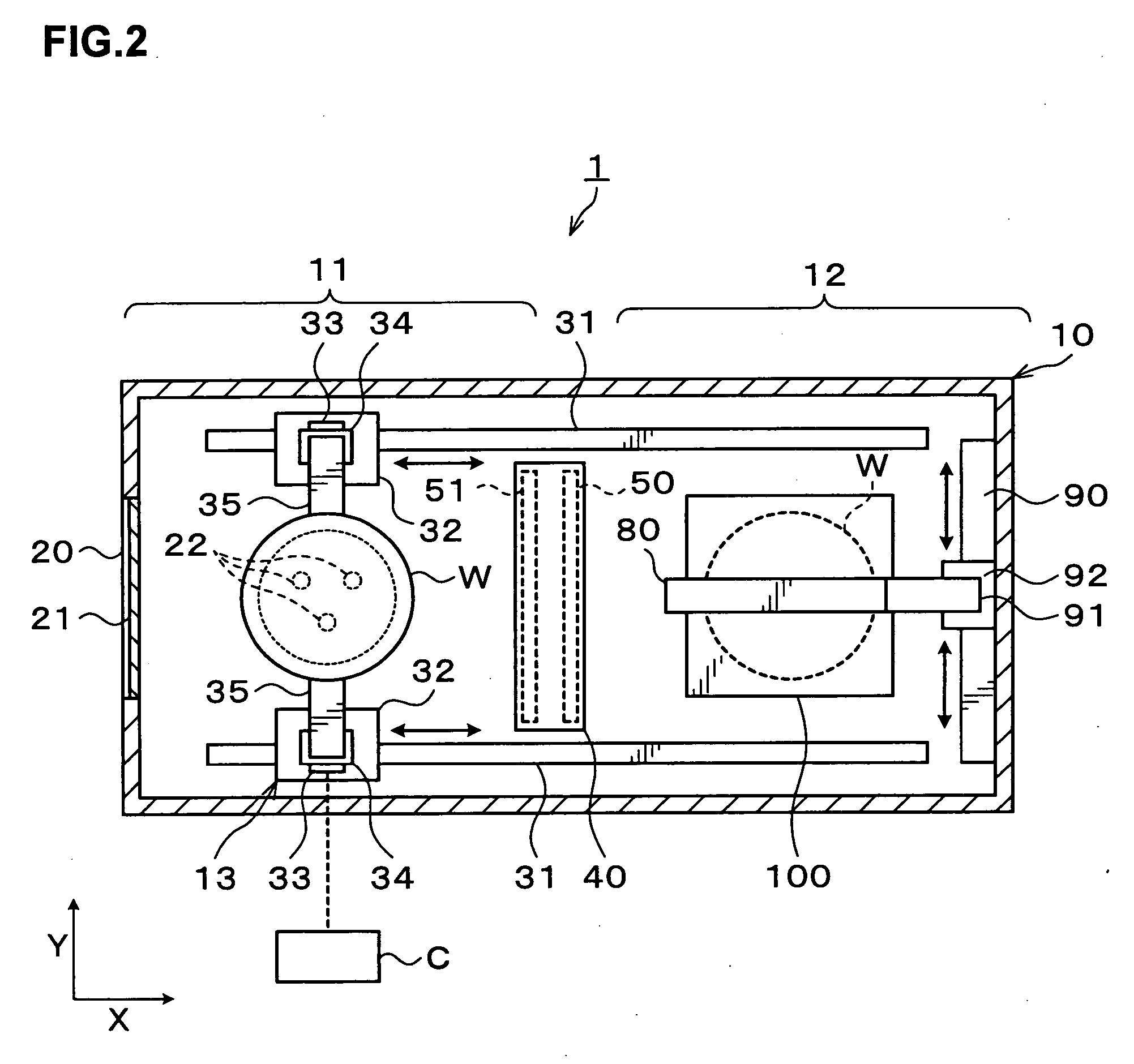
[0040] Hereinafter, preferred embodiments of the present invention will be described. FIG. 1 is an explanatory view of a longitudinal section showing the outline of a configuration of a developing treatment apparatus 1 according to this embodiment. FIG. 2 is an explanatory view of a transverse section showing the outline of the configuration of the developing treatment apparatus 1.

[0041] The developing treatment apparatus 1 includes, for example, a closable treatment container 10 as shown in FIG. 1. The treatment container 10 has an outside shape formed in an almost rectangular parallelepiped shape elongated in an X-direction (a left-to-right direction in FIG. 1). In the treatment container 10, a transfer unit 11 for transferring a wafer W to / from the outside and a developing treatment unit 12 for performing developing treatment for the wafer W are provided which are arrange side by side in the X-direction. Further, in the treatment container 10, a carrier mechanism 13 is provided ...


PUM


Abstract

In the present invention, a substrate transfer unit into/from which a substrate is transferred from/to the outside of a treatment container and a developing treatment unit in which development of the substrate is performed are arranged side by side in the treatment container, and a carrier mechanism is provided which carries the substrate while grasping an outside surface of the substrate from both sides, between the substrate transfer unit and the developing treatment unit. A developing solution supply nozzle for supplying a developing solution onto the substrate and a gas blow nozzle for blowing a gas to the substrate, are provided between the substrate transfer unit and the developing treatment unit and above a carriage path along which the substrate is carried, and a cleaning solution supply nozzle is provided in the developing treatment unit for supplying a cleaning solution onto the substrate. According to the present invention, since the substrate is carried with its outside surface being grasped, spread of contamination can be prevented to restrain generation of particles in the treatment container.

Description

BACKGROUND OF THE INVENTION [0001] 1. Field of the Invention [0002] The present invention relates to a substrate developing treatment apparatus and a developing treatment method. [0003] 2. Description of the Related Art [0004] In a photolithography process, for example, in a manufacturing process of a semiconductor device, a developing treatment of developing, for example, a wafer exposed to light under a predetermined pattern is performed. The developing treatment is generally performed in a developing treatment apparatus in such a manner that, for example, a wafer is rotated by a spin chuck, a developing solution is supplied onto the wafer from a developing solution supply nozzle to form a liquid film on the front surface of the wafer to thereby perform development of the wafer in the developing treatment. [0005] In the above-described developing treatment apparatus, however, it is necessary to rotate the wafer and thus to use a rotation motor with a high torque for the spin chuck...

Claims


Application Information

Patent Timeline
IPC IPC(8): G03D5/00
CPCG03D5/04G03F7/30H01L21/67748H01L21/6715G03F7/3021Y10S134/902
Inventor KITANO, TAKAHIROAKIMOTO, MASAMINISHIKIDO, SHUUICHIKUMAGAI, DAI
Owner TOKYO ELECTRON LTD
Why Eureka
Try Eureka