Method and apparatus for manufacturing load bearing fabric support structures

Active Publication Date: 2007-02-15
ILLINOIS TOOL WORKS INC
View PDF3 Cites 18 Cited by
  • Summary
  • Abstract
  • Description
  • Claims
  • Application Information

AI Technical Summary

Benefits of technology

[0012] The present invention provides an efficient, effective and relatively inexpensive apparatus for manufacturing load bearing fabric structures in which the frame is molded in place about the load bearing fabric. The fabric retaining assembly permits the peripheral edge of the load bearing fabric to terminate in the mold cavity, thereby eliminating the need to trim the fabric. The stretching assembly provides c

Problems solved by technology

Experience has revealed that it can be difficult to manufacture load bearing fabric structures by directly molding the fabric to support structure.
Typically, the type of materials required to withstand the loads applied to the load bearing structure are not well-suited for direct molding with the load bearing fabric.
For example, the mold conditions required to mold the frame material could damage the load bearing fabric.
The use of a separate carrier increases the manufacturing and assembly c

Method used


Image

  • Method and apparatus for manufacturing load bearing fabric support structures
  • Method and apparatus for manufacturing load bearing fabric support structures
  • Method and apparatus for manufacturing load bearing fabric support structures

Examples


Example

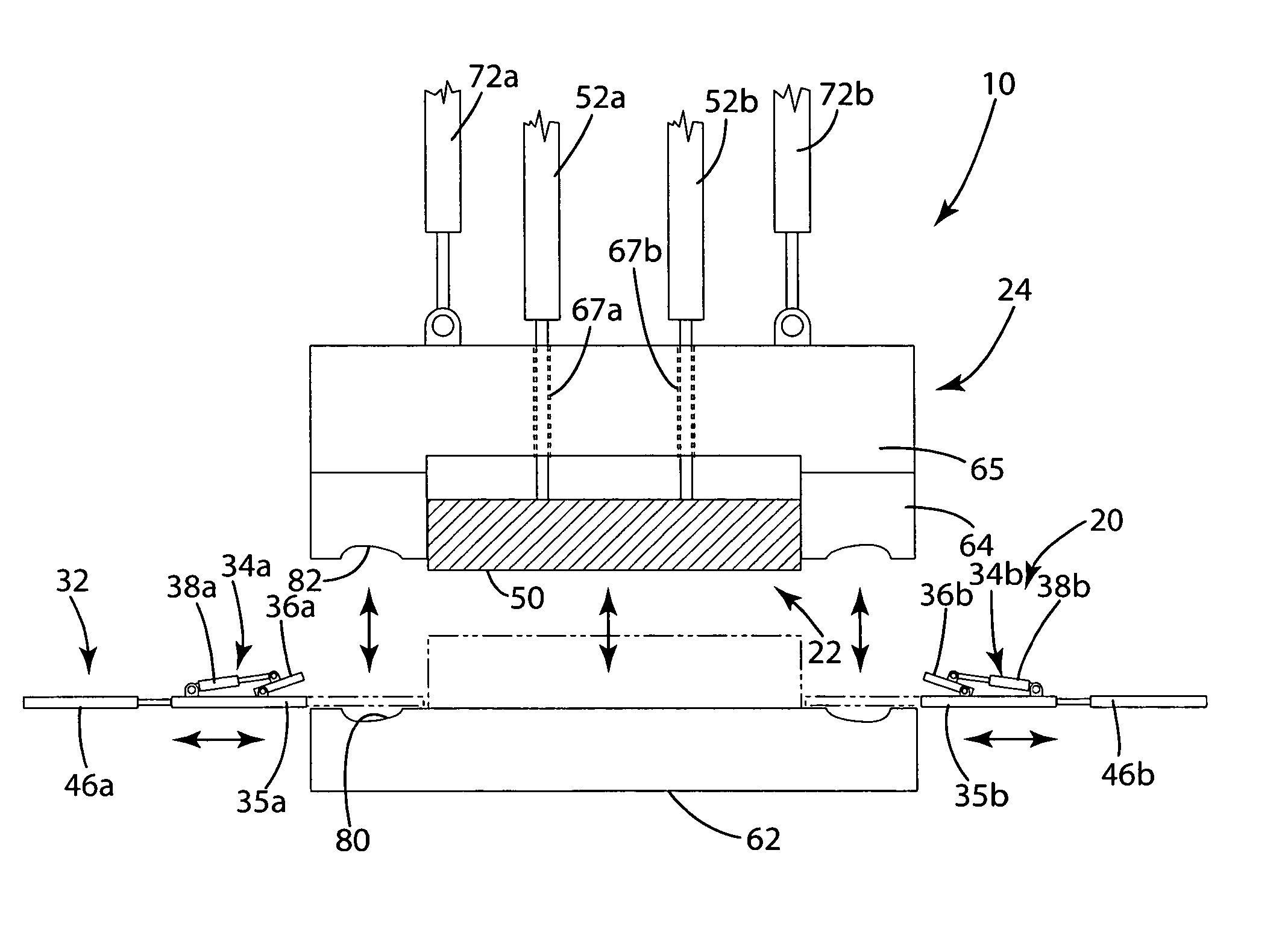
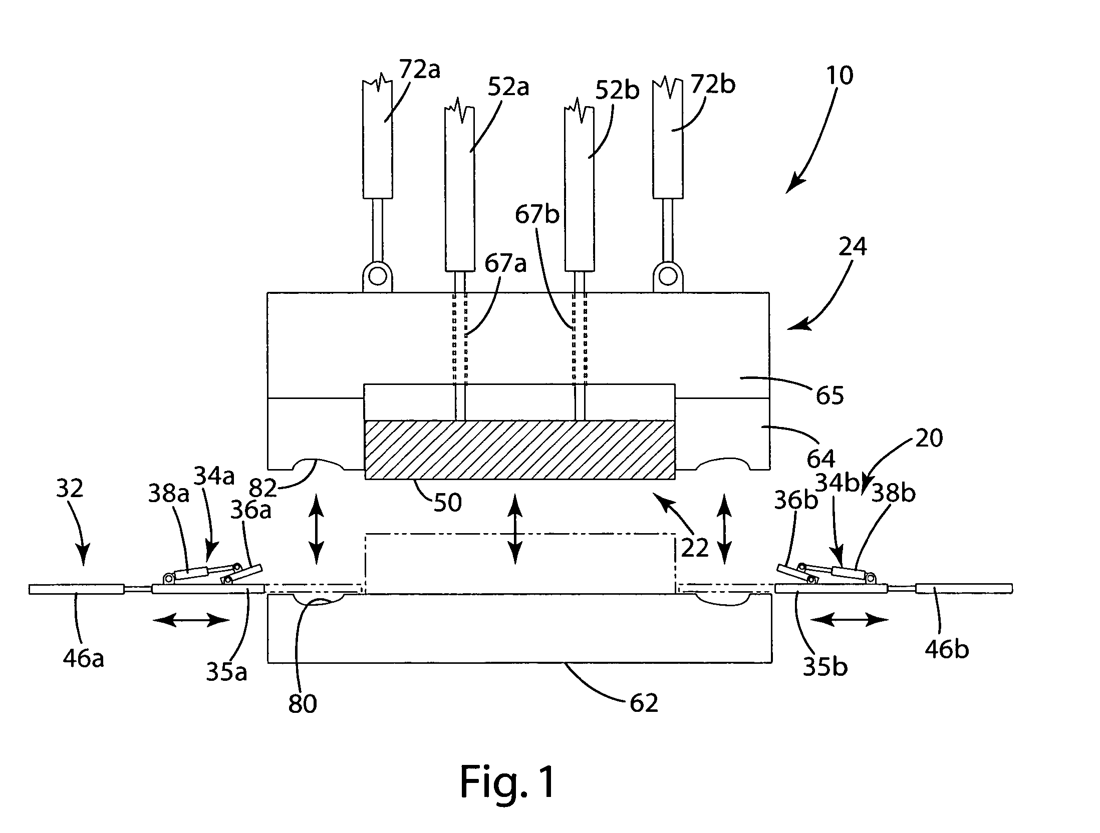
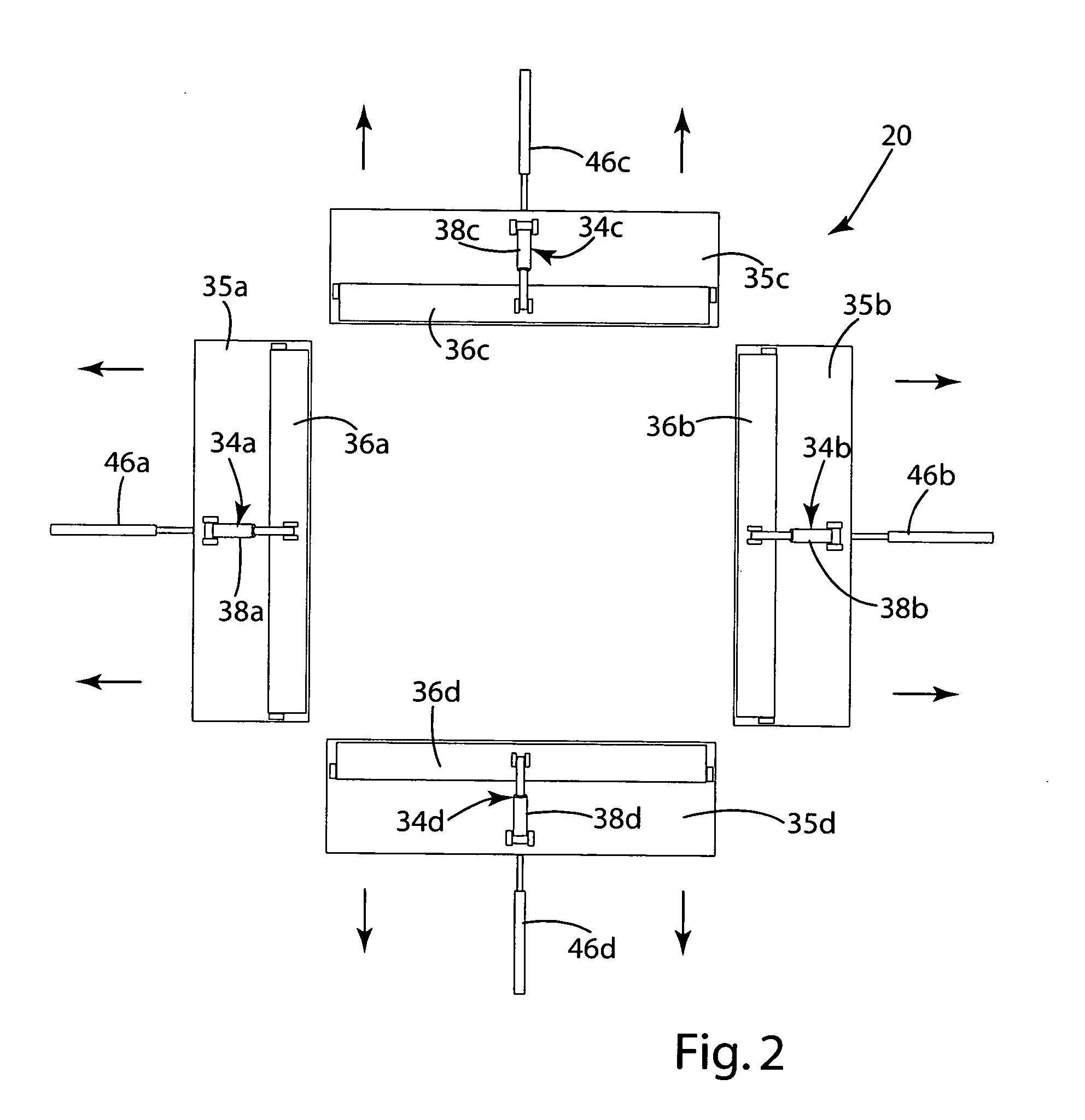
[0029] A system for manufacturing a load bearing fabric structure is shown in FIG. I and generally designated 10. The manufacturing system 10 is configured to mold a structural frame 12 directly onto the periphery of a section of pre-stretched load bearing fabric 14. The system 10 generally includes a stretching assembly 20 for stretching the load bearing fabric 14, a fabric retaining assembly 22 for holding the fabric 14 in the stretch condition after the fabric 14 has been released by the stretching assembly 20 and a mold assembly 24 for molding the frame 12 about the fabric 14 while the fabric 14 is being held by the retaining assembly 22. The present invention is described in connection with a manufacturing system 10 that is well-suited for use in the manufacture of load bearing fabric seat assemblies and back assemblies for seating applications. The present invention is, however, well-suited and may be readily implemented in manufacturing systems for other types of load bearing...


PUM

PropertyMeasurementUnit
Sizeaaaaaaaaaa
Shapeaaaaaaaaaa
Tensionaaaaaaaaaa

Abstract

A method and apparatus for manufacturing load bearing fabric structures in which the peripheral edge of the load bearing fabric terminates with the mold cavity. The apparatus includes a stretching assembly for stretching the fabric, a fabric retaining assembly for holding the fabric in the stretched condition and a mold assembly for molding the frame about the periphery of the fabric. The method includes the steps of gripping the peripheral edge of the fabric in a stretching assembly, activating the stretching assembly to stretch the fabric in a location adjacent to the mold assembly, clamping the stretched fabric against a face of the mold assembly, releasing the peripheral edge of the fabric from the stretching assembly, moving the stretching assembly from the path of the mold assembly, closing the mold assembly on the fabric with the peripheral edge of the fabric terminating in the mold cavity and injecting molten material into the mold cavity to form the frame directly on the peripheral edge of the fabric.

Description

[0001] This application claims the benefit of U.S. Provisional Patent Application No. 60 / 707,879 filed on Aug. 12, 2005.BACKGROUND OF THE INVENTION [0002] The present invention relates to support structures and more particularly to methods and apparatus relating to support structures incorporating load bearing fabric as a load bearing surface. [0003] Load bearing fabric continues to gain an increasing share of the market for load bearing surfaces. Load bearing fabrics have a variety of desirable characteristics. For example, load bearing fabrics provide a durable, high strength load bearing surface that is attractive and easily maintained. The characteristics of load bearing fabrics can be tuned to provide, among other things, a surface that is well-suited for use in seating and other body support applications. [0004] Experience has revealed that it can be difficult to manufacture load bearing fabric structures by directly molding the fabric to support structure. Typically, the type...

Claims


Application Information

Patent Timeline
IPC IPC(8): B29C70/48
CPCA47C7/282A47C31/02B29C45/14262B29C45/14336B29C70/56Y10T428/24777B29K2313/00B29K2713/00B29L2031/726Y10S264/73B29C70/76
Inventor COFFIELD, TIMOTHY P.
Owner ILLINOIS TOOL WORKS INC
Why Eureka
Try Eureka