Anode plate structure for flat panel light source of field emission

Inactive Publication Date: 2007-02-15
IND TECH RES INST
View PDF10 Cites 2 Cited by
  • Summary
  • Abstract
  • Description
  • Claims
  • Application Information

AI Technical Summary

Benefits of technology

[0005] The present invention has been made to overcome the aforementioned drawback of a conventional flat panel field emission light source. The primary object of the present invention is to provide an anode plate module of the flat panel light source of field emission. By providing an alternative structure for t

Problems solved by technology

Increasing the electron beam density degrades the lighting efficiency of the fluorescent layer.
The increase of the power also result

Method used


Image

  • Anode plate structure for flat panel light source of field emission
  • Anode plate structure for flat panel light source of field emission
  • Anode plate structure for flat panel light source of field emission

Examples


first embodiment

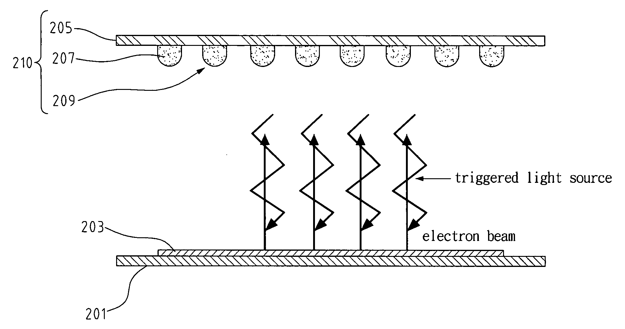
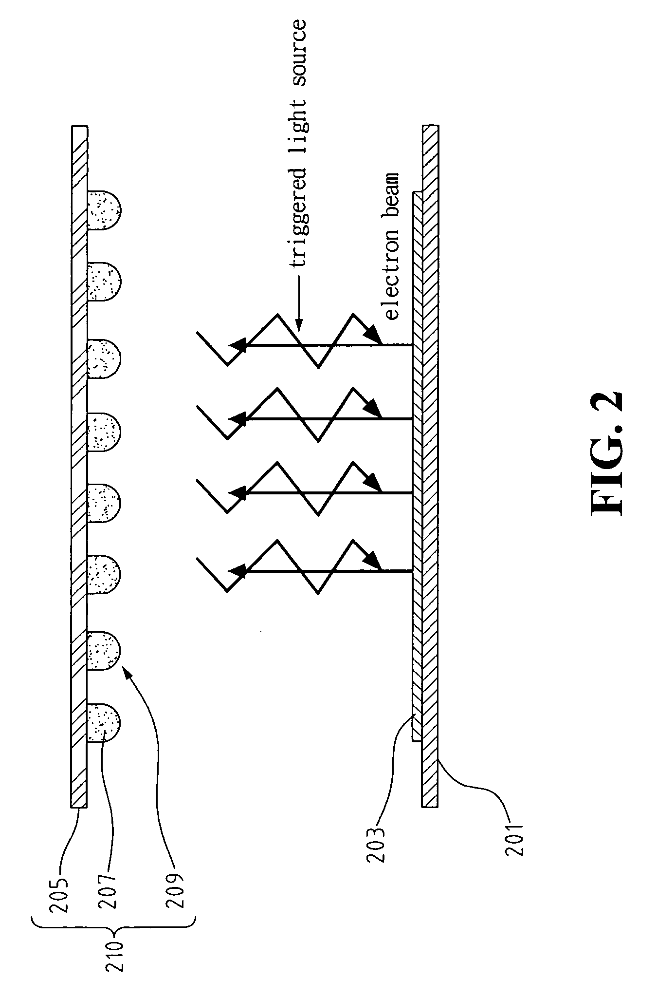
[0017] Referring to FIG. 2, in the first embodiment, the known cathode plate structure includes a cathode plate 201, plural cathode electrodes and gate electrodes formed on the cathode plate 201, and a plurality of emitters 203. The anode plate structure includes a flat anode plate 205, and a fluorescent layer 209 having a plurality of separated cubic-bumps 207 thereon.

[0018] The fluorescent layer 209 with plural cubic-bumps can be formed by coating the surface of the flat anode plate with the fluorescent paste via a screen printing method.

[0019] In the following second embodiment and the third embodiment of the present invention, the cathode plate structure is identical to that of the first embodiment. For the anode plate structure, the anode plate of the second and the third embodiments comprises a rough surface structure.

second embodiment

[0020] Referring to FIG. 3, in this second embodiment, the anode plate structure 310 comprises an anode plate 305 with a rough surface 306, and a fluorescent layer 309 formed on the rough surface 306. The anode plate 305 comprises a cubic concave-convex structure 307. The fluorescent layer 309 is formed on the surface of this cubic concave-convex structure 307. The cubic concave-convex structure 307 can be formed on a flat substrate with a plurality of convex cubic-bumps. The rough surface structure 306 of the anode plate 305 can be also formed by varieties of methods like etching or sand spray.

[0021] Compared with the surface area of the anode plate in the first embodiment, the cubic concave-convex structure 307 of the rough surface 306 in the second embodiment has larger surface area for the coating of fluorescent paste. With the increased hit ratio of the electron beam under the same condition of electron density and anode plate voltage, the resulting luminescent efficiency can t...


PUM


Abstract

This invention provides an anode plate structure for a flat panel light source of field emission. The structure for the flat panel light source includes an anode plate structure in addition to a known cathode plate structure. The anode plate structure comprises an anode plate and a fluorescent layer formed on the anode plate. The flat panel light source utilizes a cubic-bump structure of the fluorescent layer or a rough surface of the anode plate to increase the lighting areas per unit volume, thereby enhancing the lighting effect of the light source. In the embodiments of the flat panel light source, the rough surface of the anode plate may be formed with a plurality of cubic-bumps, or have a shape of plural concave lenses.

Description

FIELD OF THE INVENTION [0001] The present invention generally relates to a field emission display (FED) and more specifically to an anode plate structure for a flat panel light source of field emission. BACKGROUND OF THE INVENTION [0002]FIG. 1 shows a schematic view of a conventional flat panel field emission light source comprising a cathode plate module and an anode plate module. The cathode plate module mainly includes a cathode plate 101, a plurality of emitters 103, a plurality of cathode electrodes and a plurality of gate electrodes. The cathode electrodes and a plurality of gate electrodes (not shown in FIG. 1) are formed on the surface of the cathode plate 101. The anode plate module mainly includes a substrate 105, a indium tin oxide (ITO) layer 107 formed on the inner surface of the substrate 105, and a fluorescent layer 109. [0003] Electron beams emitted from the emitters 103 at a low drive voltage, strike the fluorescent layer 109 which is on the top of the ITO layer, an...

Claims


Application Information

Patent Timeline
IPC IPC(8): H01J1/62H01J63/04
CPCH01J29/862H01J63/04H01J63/02H01J31/127
Inventor LIN, MING-HUNGCHANG, YU-YANGLIN, WEI-YILEE, CHENG-CHUNG
Owner IND TECH RES INST
Why Eureka
Try Eureka