Switching regulator

a technology of switching regulator and switch, which is applied in the direction of power conversion system, dc-dc conversion, instruments, etc., can solve problems such as inability to operate pwm, and achieve the effects of good stability, enhanced protection function, and good respons

Inactive Publication Date: 2007-02-15
RENESAS ELECTRONICS CORP
View PDF16 Cites 52 Cited by
  • Summary
  • Abstract
  • Description
  • Claims
  • Application Information

AI Technical Summary

Benefits of technology

[0012] It is possible to achieve a switching regulator having good stability compatible with a good response. By utilizing two feedback paths provided to make good stability compatible with a good response, the protection function can be enhanced.

Problems solved by technology

It has been found that the attempt to improve the load regulation by additionally providing the error amplifier, as in the switching regulator described in the above Patent Document 2, poses the following problem.
As the graph (A)+(B) indicates, the load regulation is seen to improve in a low frequency domain, but the error amplifier has a constant gain for a PWM frequency band fPWM and thus amplifies even a ripple in the output voltage in synchronization with PWM, resulting in unstable PWM operation.

Method used


Image

  • Switching regulator
  • Switching regulator
  • Switching regulator

Examples


Embodiment Construction

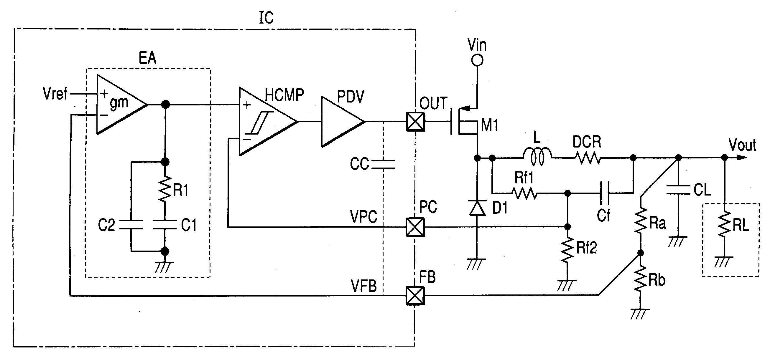
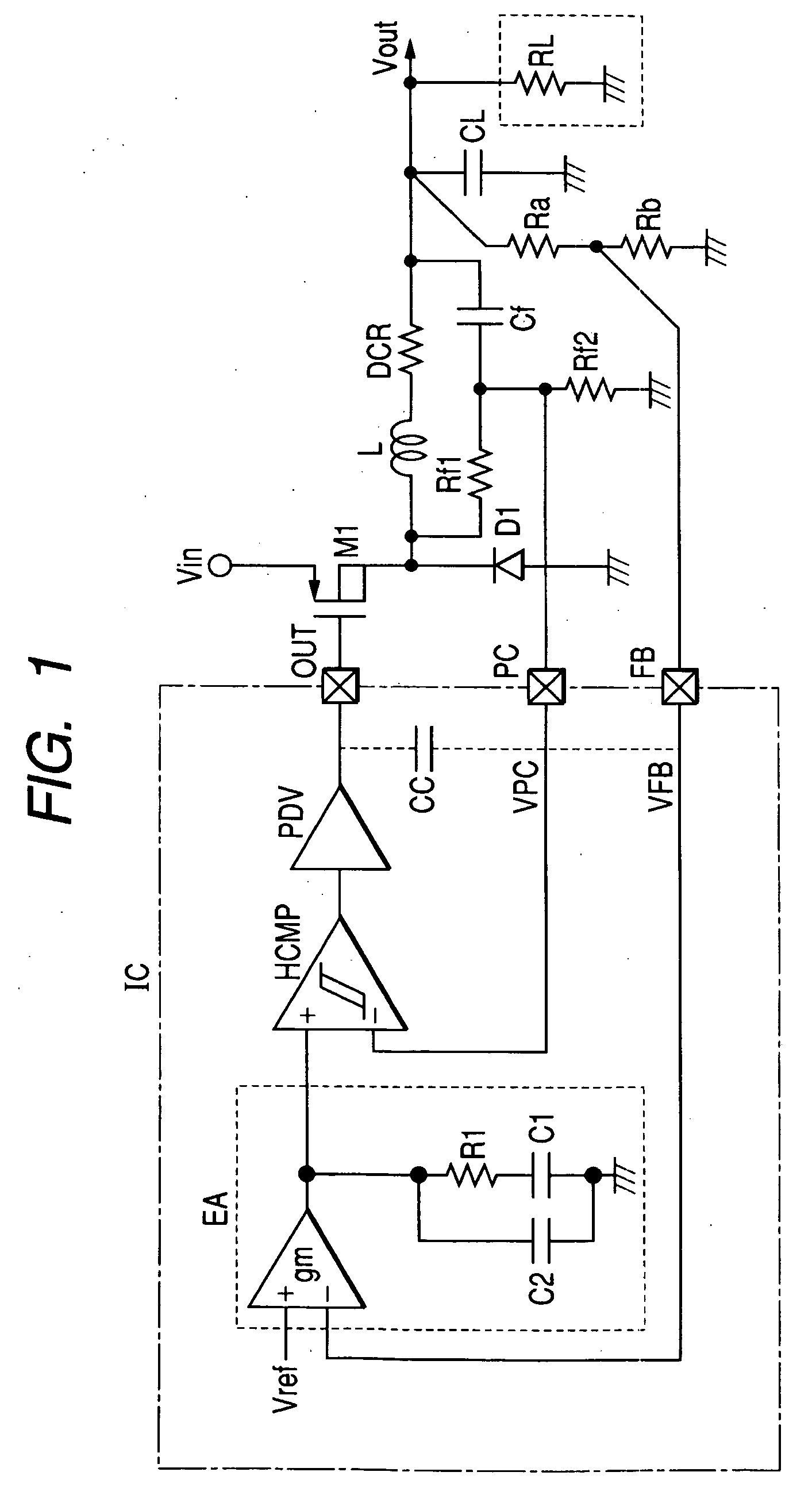
[0025]FIG. 1 shows a circuit diagram of one embodiment of a switching regulator according to this invention. To a voltage input terminal of the switching regulator of this embodiment, a DC voltage Vin is supplied from a DC power supply such as a battery cell. This voltage input terminal is connected to a source of a MOSFET M1 as a switching element. Thus, the MOSFET M1 is a P-channel MOSFET. A drain of the MOSFET M1 is connected to a cathode electrode of a diode D1. An anode electrode of the diode D1 is connected to a ground potential terminal. The drain of the MOSFET M1 is connected to an input end of an inductor (coil) L. An output end of the inductor L is connected to an output terminal for an output voltage Vout. A resistor DCR represents an equivalent DC resistance included in the inductor L. A smoothing capacitor CL is placed between the output terminal and a ground point.

[0026] A resistor Rf1 and a capacitor Cf which are connected in series are connected in parallel to the a...


PUM


Abstract

The present invention provides a switching regulator having good stability compatible with a good response and an enhanced protection function. A first capacitor is placed between an output end of an inductor to generate an output voltage and a ground potential. From input voltage, a current is supplied to the inductor's input end by a first switch element. A first feedback path includes a hysteretic comparator. An output voltage added to a voltage proportional to the current flowing through the inductor is supplied to the hysteretic comparator which discriminates whether the voltage is appropriate by hysteresis characteristics and generates a PWM control signal in accordance with an output current variation. Moreover, a second feedback path is provided to feed back an error amplifier output voltage with greater gain in a low frequency domain and an attenuation loop around a PWM frequency band to the comparator's reference voltage input terminal. Feedback voltage through the second feedback path is used as a monitoring voltage in a protection circuit.

Description

CROSS-REFERENCE TO RELATED APPLICATION [0001] The present application claims priority from Japanese application No. 2005-232927 filed on Aug. 11, 2005, the content of which is hereby incorporated by reference into this application. BACKGROUND OF THE INVENTION [0002] The present invention relates to a switching regulator for generating a DC voltage and a technique that is effectively applicable to a switching regulator required to have a good transient response, or a technique that is effectively utilized for, for example, a switching regulator provided in a system with a large variation in consumption current. [0003] Lately, electronic devices in which a microprocessor is embedded as a system controller are increasing. The operating frequency of the microprocessor (hereinafter referred to as CPU) tends to become higher and higher and the maximum operating current increases, as the operating frequency increases. Meanwhile, portable or similar electronic devices incorporating the CPU ...

Claims


Application Information

Patent Timeline
Patent Type & Authority Applications(United States)
IPC IPC(8): G05F1/00
CPCH02M2001/0022H02M3/156H02M1/0022
Inventor KUROIWA, HIROSHIKOKAMI, YASUHIKOYAMASHITA, OSAMU
Owner RENESAS ELECTRONICS CORP
Why Eureka
Try Eureka