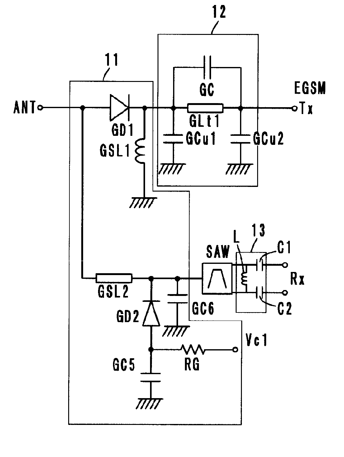
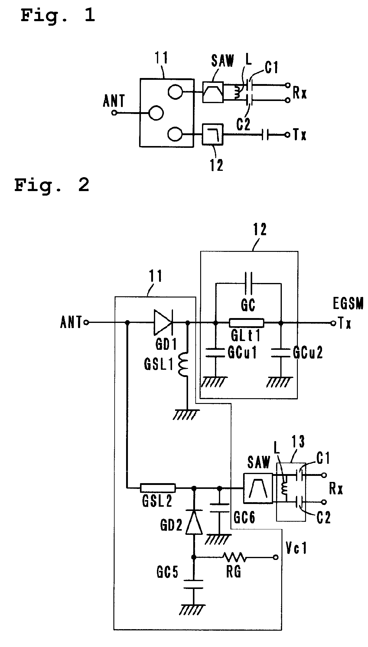
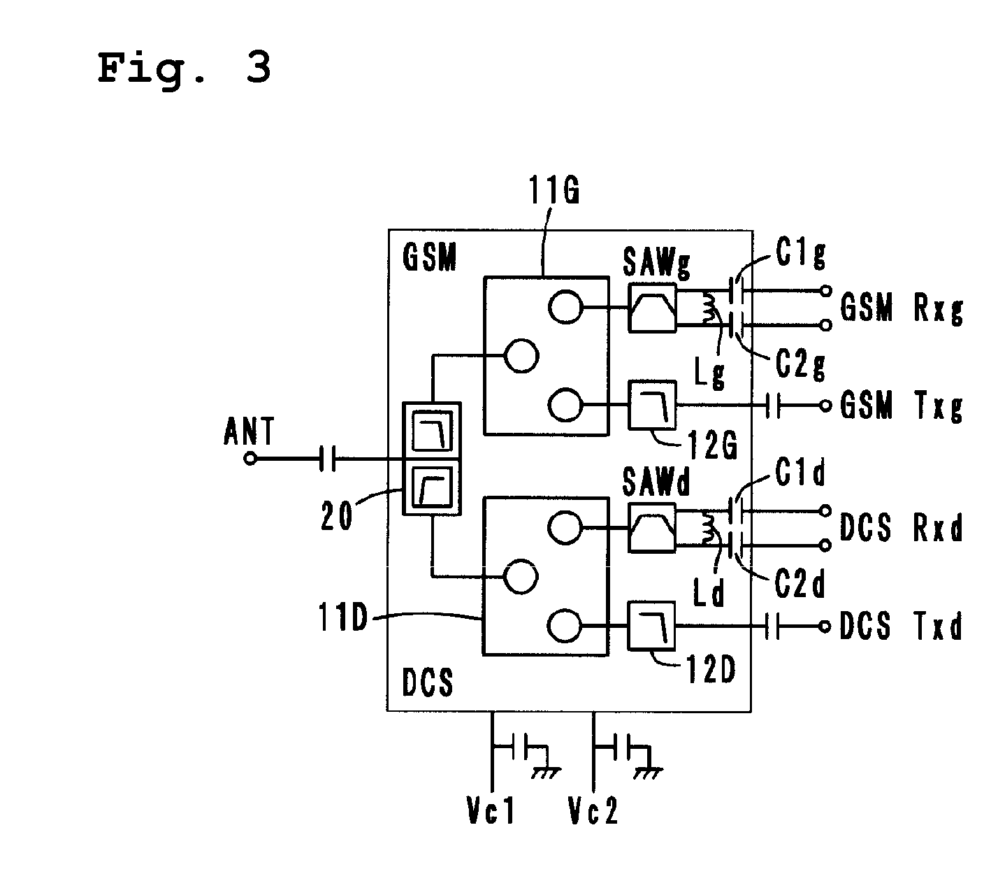
High frequency composite component

a composite component and high frequency technology, applied in the direction of fixed capacitor details, filters, fixed capacitors, etc., can solve the problems of increasing the size of the equipment, the difficulty of setting a desired impedance, and the number of components and the mounting area, so as to reduce the overall size and reduce the number of components.

Active Publication Date: 2007-02-15
MURATA MFG CO LTD
View PDF15 Cites 18 Cited by
  • Summary
  • Abstract
  • Description
  • Claims
  • Application Information

AI Technical Summary

Benefits of technology

[0009] To overcome the problems described above, preferred embodiments of the present invention provide a high-frequency composite component in which a desired impedance is easily set in the high-frequency composite component itself, no matching adjustment to an LNA is required, the number of components is reduced, and the overall size is reduced.

Problems solved by technology

However, it is difficult to set a desired impedance (complex impedance, in particular).
However, when capacitors and inductors as separate components are added between such a high-frequency composite component and an LNA, the number of components and the mounting area increase which increases the size of the equipment, and the matching between the bandpass filter 5 and the LNA becomes more complicated.

Method used


Image

  • High frequency composite component
  • High frequency composite component
  • High frequency composite component

Examples


fifth preferred embodiment (fig.16)

Fifth Preferred Embodiment (FIG. 16)

[0101] A high-frequency composite component according to a fifth preferred embodiment is a triple-band type, as shown in an equivalent circuit of FIG. 16. The structure is basically the same as that of the fourth preferred embodiment (see FIG. 11) and the operation effect is also the same as the fourth preferred embodiment. The different between the fifth preferred embodiment and the fourth preferred embodiment is that the reception-side balanced output terminals Rxd1 and Rxd2 are separated by a diode switch 15D, instead of by the duplexer 14D.

[0102] The diode switch 15D includes diodes SDD1 and SDD2 as switching elements, inductors SID1 and SID2, capacitors SC1, SC2, and SC3, and a resistor SR. A first port P51d is connected to the third port P33d of the second high-frequency switch 11D′, and the other end of the capacitor SC3, one end of which is connected to the first port P51d, is connected to the anode of the diode SDD2 through the cathode o...

sixth preferred embodiment (fig.17)

Sixth Preferred Embodiment (FIG. 17)

[0104] A high-frequency composite component according to the sixth preferred embodiment is a triple-band type high-frequency composite component, as shown in FIG. 17. The structure is basically the same as that of the fourth preferred embodiment (see FIG. 11) and the operation effect is also the same as in the fourth preferred embodiment. The difference is that the surface acoustic wave filters SAWd1 and SAWd2 having unbalanced output ports are of an unbalanced type and the matching elements 13D1 and 13D2 connected to the unbalanced output ports are defined as baluns.

Other Embodiments

[0105] Moreover, the high-frequency composite components according to the present invention are not limited to the above-described embodiments, and various modifications can be made without departing from the spirit and the scope of the invention.

[0106] For example, in the above-described preferred embodiments, high-frequency composite components of a single-band ...


PUM


Abstract

A high-frequency composite component for selectively switching a GSM-system signal path and a DCS-system signal path for a signal transmitted to or received from an antenna terminal by a diplexer. Transmission-side input terminals and reception-side balanced output terminals to be switched by high-frequency switches are included in the GSM and the DCS systems. Matching elements include inductors and capacitors that are inserted between the reception-side balanced output terminals and the output side of surface acoustic wave filters.

Description

BACKGROUND OF THE INVENTION [0001] 1. Field of the Invention [0002] The present invention relates to a high-frequency composite component, and more particularly, to a high-frequency composite component for use in a plurality of different mobile communication systems. [0003] 2. Description of the Related Art [0004] Presently, in Europe, as a mobile communication device, a dual-band portable telephone has been proposed which can operate in a plurality of frequency bands, for example, in the DCS system using a 1.8 GHz band and the GSM system using a 900 MHz band. [0005]FIG. 18 shows a portion of the structure of a general dual-band portable telephone which includes an antenna 1, a diplexer 2, and two signal paths of a DCS system 3 (1.8 GHz band) and a GSM system 4 (900 MHz band). [0006] The diplexer 2 selects a transmission signal from the DCS system 3 or the GSM system 4 in transmission and selects a reception signal to the DCS system 3 or the GSM system 4 in reception. The DCS system...

Claims


Application Information

Patent Timeline
Patent Type & Authority Applications(United States)
IPC IPC(8): H03H9/72
CPCH03H7/46H03H7/465H03H9/0576H04B1/48H03H9/725H03H2250/00H04B1/406H03H9/72H01P1/15
Inventor UEJIMA, TAKANORINAKAYAMA, NAOKIHARADA, TETSUROKOYAMA, KUNIHIRO
Owner MURATA MFG CO LTD
Why Eureka
Try Eureka