
Apparatus and method for determining centering data for spectacles

Active Publication Date: 2007-02-15
CARL ZEISS VISION INT GMBH
View PDF5 Cites 13 Cited by
  • Summary
  • Abstract
  • Description
  • Claims
  • Application Information

AI Technical Summary

Benefits of technology

[0013] The convergence comprises a motoric component and a sensoric component of the pair of eyes. The motoric component is the convergence component effected by muscle movement and the sensoric component is the convergence component effected by the interconnection of nerve cells. The totality of the occurrences is characterized as fusion and the occurrences lead to simple binocular viewing and maintain this because of the fusion stimuli emanating from the objects. These occurrences are substantially subconscious. The motoric fusion and sensoric fusion interact with each other. With the aid of the eye movement muscles, fusion effects a vergency in order to direct the eyes as accurately as possible on the fusion object. Sensoric fusion effects binocular viewing of one image with the aid of switching operations in the nervous system even with slight disparity, that is, when the two monocular images do not lie precisely on the corresponding retina locations with these two monocular images belonging together.
[0027] The collimator optic can be realized by conventional spherical lens surfaces. In order to keep the influence of the spherical aberration low, the focal width of the lens should be selected correspondingly large, for example, f′=800 to 1200 mm, preferably f′=1000 mm, so that the aperture ratio is tolerable. The collimator optic can be configured with aspheric lens surfaces, especially with aspherical Fresnel lens surfaces. In this way, the correction of the spherical aberration can also take place even when using smaller lens focal lengths such as f′=300 mm. With the use of aspherical Fresnel lenses, the mechanical complexity is clearly reduced for the lens holder. With the use of spherical Fresnel lens profiles, a focal length of at least 500 mm should be used.
[0029] In a preferred embodiment of the apparatus of the invention, it can be provided that a deflecting mirror be mounted between the diffusion element and the divider element and preferably between the diffusion element and the collimator optic. With a folding of the optical assembly (that is, with a beam deflection), the structural size of the apparatus can be significantly reduced.
[0037] With the method and apparatus of the invention, it is made possible for test persons of different visual acuity to measure their relative centering data in their habitual posture at a short distance.

Problems solved by technology

It is disadvantageous here that the convergence position of the pair of eyes is approximated via the purely geometric convergence.

Method used


Image

  • Apparatus and method for determining centering data for spectacles
  • Apparatus and method for determining centering data for spectacles
  • Apparatus and method for determining centering data for spectacles

Examples


Embodiment Construction

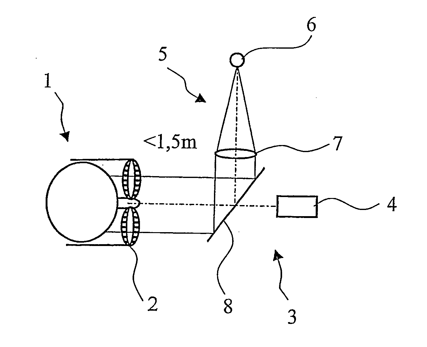
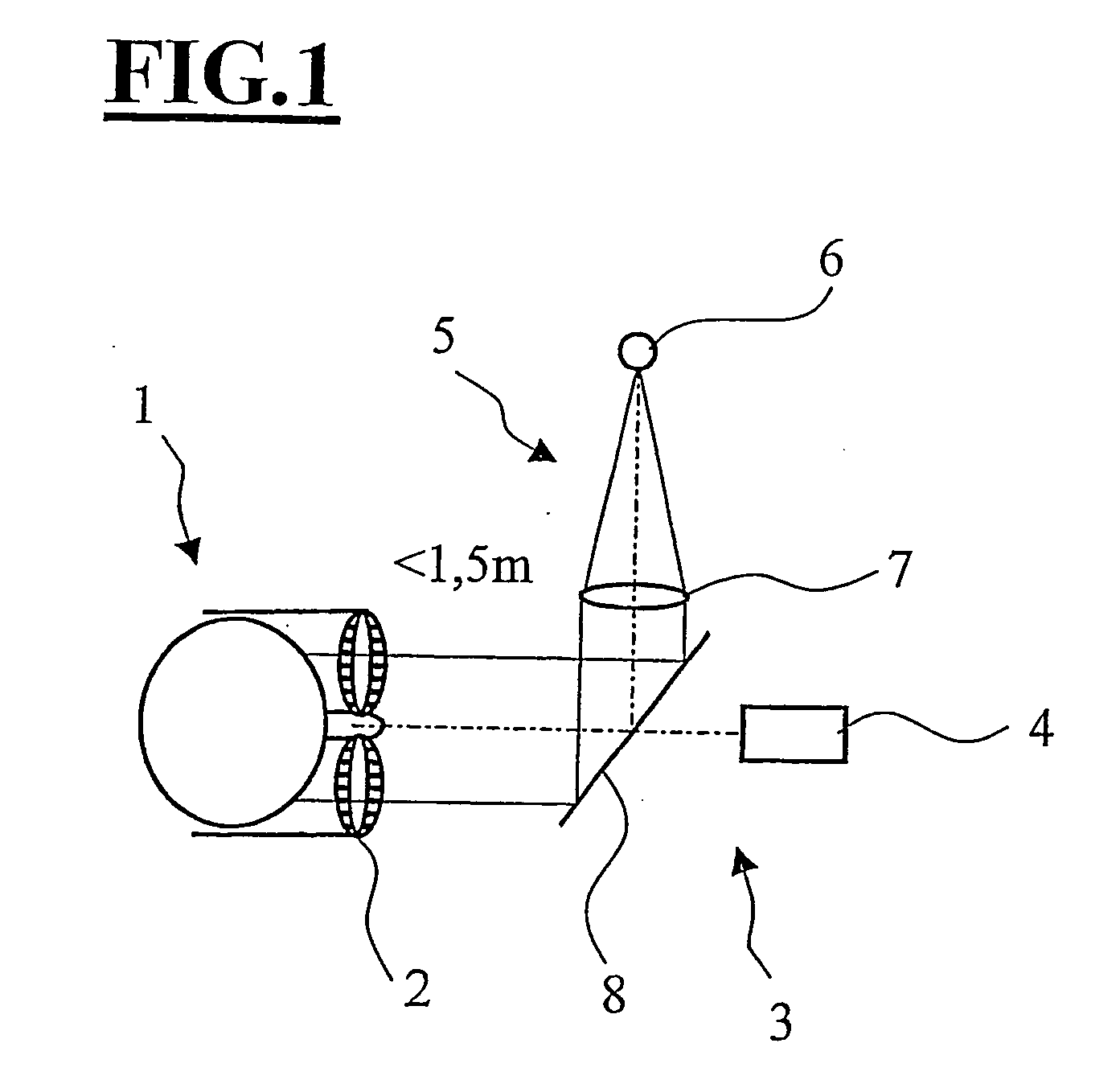
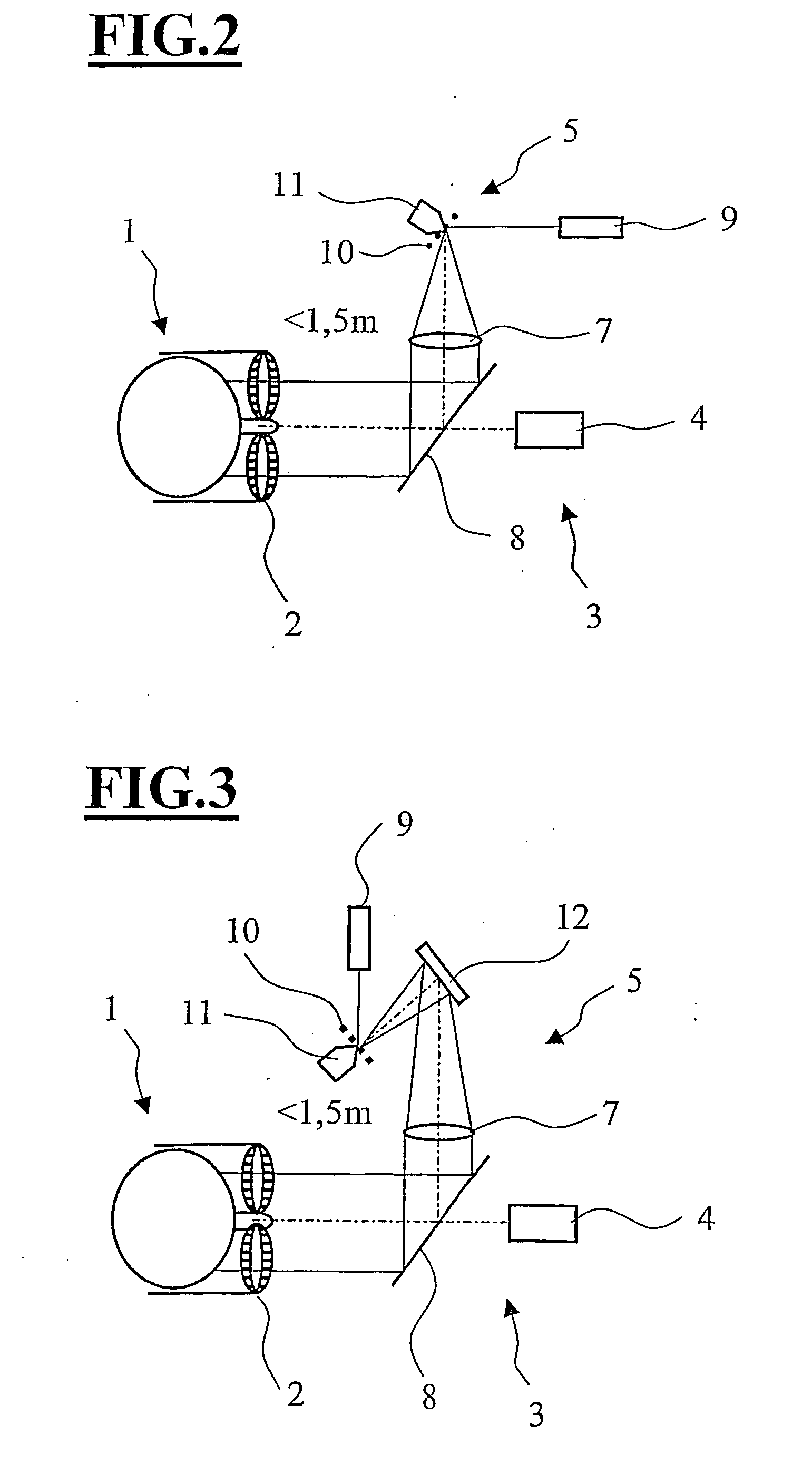
[0048]FIG. 1 shows schematically the head 1 of a test person wearing a frame 2 of a pair of spectacles. The test person looks into an embodiment of the apparatus 3 of the invention at a distance of less than 1.5 m (for example, 0.5 m) to determine the centering data of the test person. The apparatus 3 is likewise shown schematically and includes a recording unit in the form of a video device 4 and a fixating device 5. The fixating device 5 includes a fixating target 6 as well as a collimator optic 7 and a divider element 8. The fixating target 6 generates a speckle pattern in that coherent light is directed onto a diffusion element (not shown), for example, a diffusion disc of defined roughness. The divider element 8 is configured as a partially-transmitting mirror. The collimating optic 7 can include one or several lenses.

[0049] In FIG. 2, a laser emitter 9 is provided in lieu of the fixating target 6. The laser emitter 9 casts a light beam onto a diffusion element in the form of ...


PUM


Abstract

An apparatus (3) for determining centering data for eyeglasses (2) comprises a fixation device (5) and a recording unit (4) that can be triggered by a computer, records electronic images, and is disposed behind a divider element (8). The fixation device (5) produces at least one speckle pattern. The speckles can be superposed by different patterns, for example, a cross shape. The invention further relates to a method for determining centering data. The inventive method and apparatus allow test persons having the most different acuity of vision to measure the relative centering data from a short distance while maintaining their usual posture.

Description

CROSS REFERENCE TO RELATED APPLICATIONS [0001] This application is a continuation application of international patent application PCT / EP 2005 / 000390, filed Jan. 14, 2005, and claiming priority from German application nos. 10 2004 002 651.3, filed Jan. 16, 2004, and 10 2004 045 013.7, filed Sep. 15, 2005, and the entire content of these applications is incorporated herein by reference.FIELD OF THE INVENTION [0002] The invention relates to an apparatus for determining centering or centration data for spectacles having a recording unit which is mounted behind a divider element and has a fixating device. The recording unit records electronic images and is driveable by a computer. The invention also relates to a method for determining centering data for spectacles. BACKGROUND OF THE INVENTION [0003] Apparatus for fitting spectacles serve to precisely determine the optical centering for spectacle frames already fitted anatomically. The vertical distance of the center point from the zero v...

Claims


Application Information

Patent Timeline
IPC IPC(8): G02C7/06G02C13/00
CPCG02C13/005
Inventor ROSS-MESSEMER, MARTINKUBITZA, MATTHIASHOLLER, FRANKKRUG, HERBERTWEGENDT, HOLGER
Owner CARL ZEISS VISION INT GMBH
Learn More