Check patentability & draft patents in minutes with Patsnap Eureka AI!

Exposure method

Inactive Publication Date: 2007-02-15
CANON KK
View PDF4 Cites 15 Cited by
  • Summary
  • Abstract
  • Description
  • Claims
  • Application Information

AI Technical Summary

Benefits of technology

[0008] The present invention is directed to an exposure method that can manufacture a device as a final product with a good yield rate.

Problems solved by technology

As finer processing advances, an interaction between processes in the device manufacturing method becomes non-negligible, and the yield rate control over exposure only using the CD uniformity cannot necessarily improve the yield rate.
For example, even when the CD uniformity is bad, the device is not defective in view of the electrical characteristic, and even when satisfying a predetermined CD uniformity, the device is defective in view of the electrical characteristic.

Method used


Image

  • Exposure method
  • Exposure method
  • Exposure method

Examples


Embodiment Construction

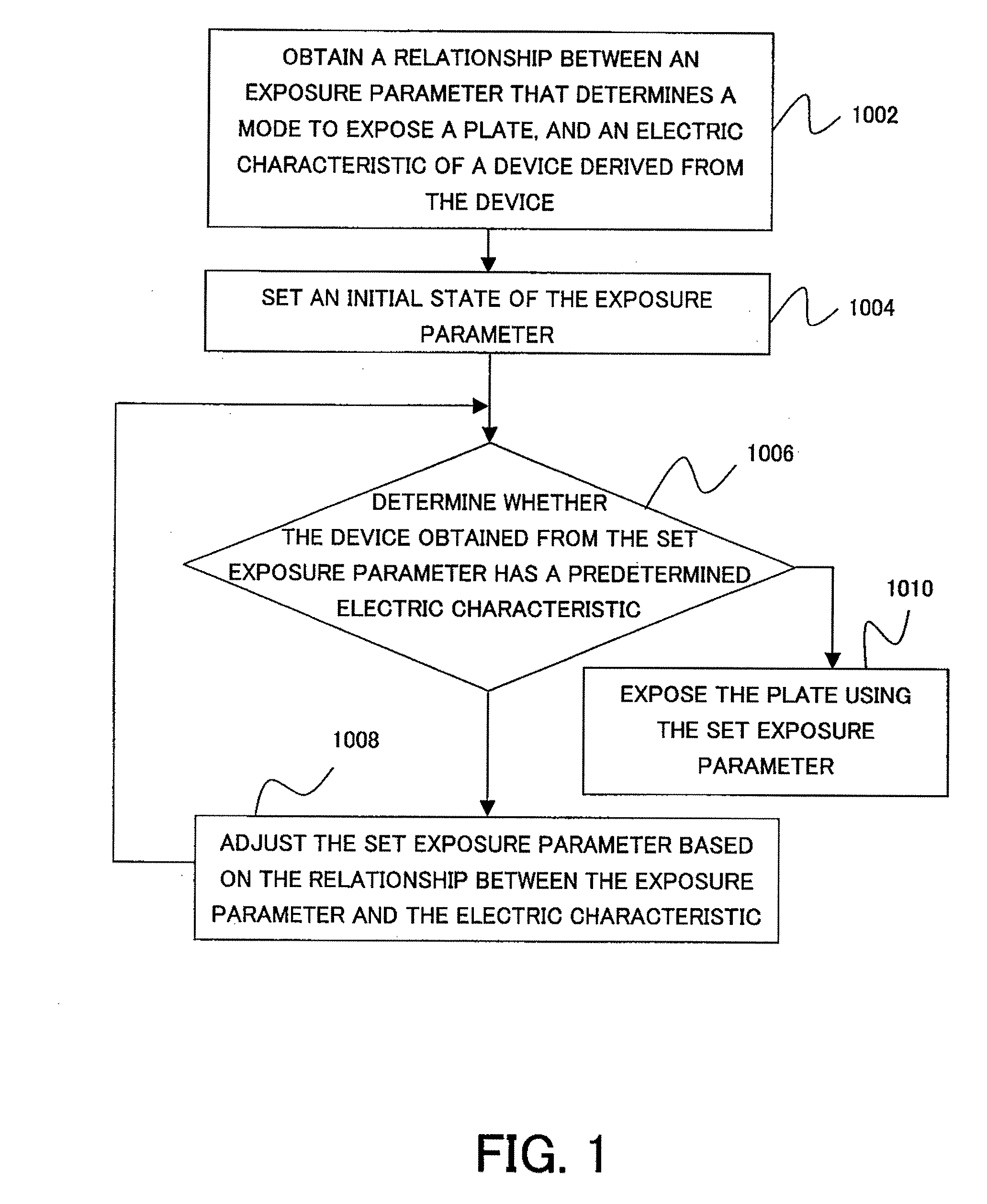
[0025] Referring now to the accompanying drawings, a description will be given of the preferred embodiments of the present invention. FIG. 1 is a flowchart of an optimization algorithm of this embodiment. FIG. 4 shows an exposure system 1 that executes the optimization algorithm shown in FIG. 1. The exposure system 1 includes, as shown in FIG. 4, a processing system 10 in a FAB (factory), input parts 20a-20c, an operating system 30, and exposure apparatuses 40a-40d.

[0026] The processing system 10 obtains reticle data and exposure condition from the input parts 20a to 20c, and selects an appropriate one of the exposure apparatuses 40a to 40d. The exposure apparatuses 40a to 40d have different characteristic data and specifications, such as a light source (ArF, KrF, EUV etc.), an exposure method (scanner, stepper, etc.), an illumination condition (polarization illumination, effective light source, etc.), and a projection optical system (dioptric, catadioptric, immersion system, etc.)...


PUM


Abstract

An exposure method for exposing a pattern of a reticle onto a plate using a light from a light source and an optical system includes the steps of obtaining a relationship between an exposure parameter that determines a mode to expose a plate, and an electrical characteristic of a device derived from the device, determining whether the device obtained from the set exposure parameter has a predetermined electrical characteristic, and adjusting the set exposure parameter based on the relationship between the exposure parameter and the electrical characteristic, if the determining step determines that the device does not have the predetermined electrical characteristic.

Description

BACKGROUND OF THE INVENTION [0001] The present invention relates generally to an exposure method, and more particularly to an optimization of an exposure condition. [0002] A conventional projection exposure apparatus uses a projection optical system to expose a reticle (or mask) pattern onto a plate, such as a single crystal substrate for a semiconductor wafer, and a glass plate for a liquid crystal display. In order to meet a demand for inexpensively supplying many electronic apparatuses, a method for manufacturing a device, such as a semiconductor chip (e.g., an LSI, a VLSI), a CCD, an LCD, a magnetic sensor, and a thin-film magnetic head), needs to improve the yield rate. This device manufacturing method includes various processes, such as exposure, development, and etching. In exposure, a conventional exposure apparatus considers not only the resolution at which the reticle pattern precisely resolve on a plate to be exposed, but also the influence on the other processes in the d...

Claims


Application Information

Patent Timeline
IPC IPC(8): G03C5/00G03B27/72G03B27/32
CPCG03F7/705G03F7/70658G03F7/70525G03F7/70141G03F7/70258G03F7/70483
Inventor YOSHII, HIROTOMORI, KENICHIRO
Owner CANON KK
Features
  • R&D
  • Intellectual Property
  • Life Sciences
  • Materials
  • Tech Scout
  • Unparalleled Data Quality
  • Higher Quality Content
  • 60% Fewer Hallucinations
Learn More