High pass modulation of a phase locked loop

a phase locked loop and high pass modulation technology, applied in the field of radio frequency modulators, can solve the problems of insufficient gain of pre-compensation filters, unrealistic gain of compensation filters, and inability to achieve pre-compensation filters

Active Publication Date: 2007-02-15
NOKIA TECHNOLOGLES OY
View PDF2 Cites 63 Cited by
  • Summary
  • Abstract
  • Description
  • Claims
  • Application Information

AI Technical Summary

Benefits of technology

[0035] operating the direct modulator as a high-pass direct modulator by feeding a ...

Problems solved by technology

This kind of pre-compensation filter is, however, not feasible.
For example, in those frequency areas in which the gain of the low-pass PLL transfer function is very low the gain of the compensation filter should be unrealistically high.
If there were a transfer null in the low-pass PLL transfer function on the frequency range of the modulation signal, any (finite) gain of the pre-compensation filter would not be sufficient.
Two-point direct modulation is quite demanding dealing with quality of gain and delay balances between a low-pass path and a high-pass path.
If a signal via one path is too strong or in an improper phase shift with respect to a signal via anot...

Method used


Image

  • High pass modulation of a phase locked loop
  • High pass modulation of a phase locked loop
  • High pass modulation of a phase locked loop

Examples


Embodiment Construction

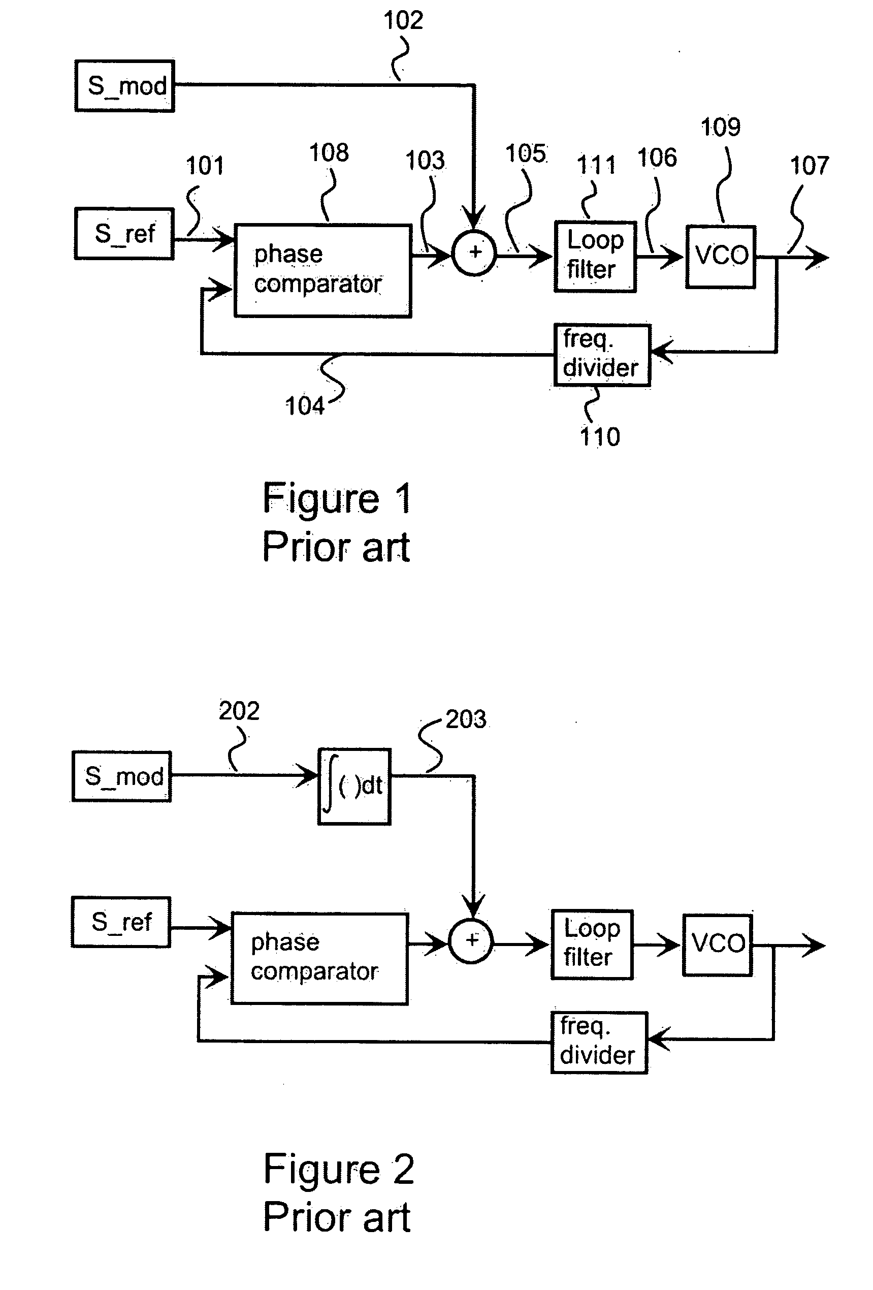
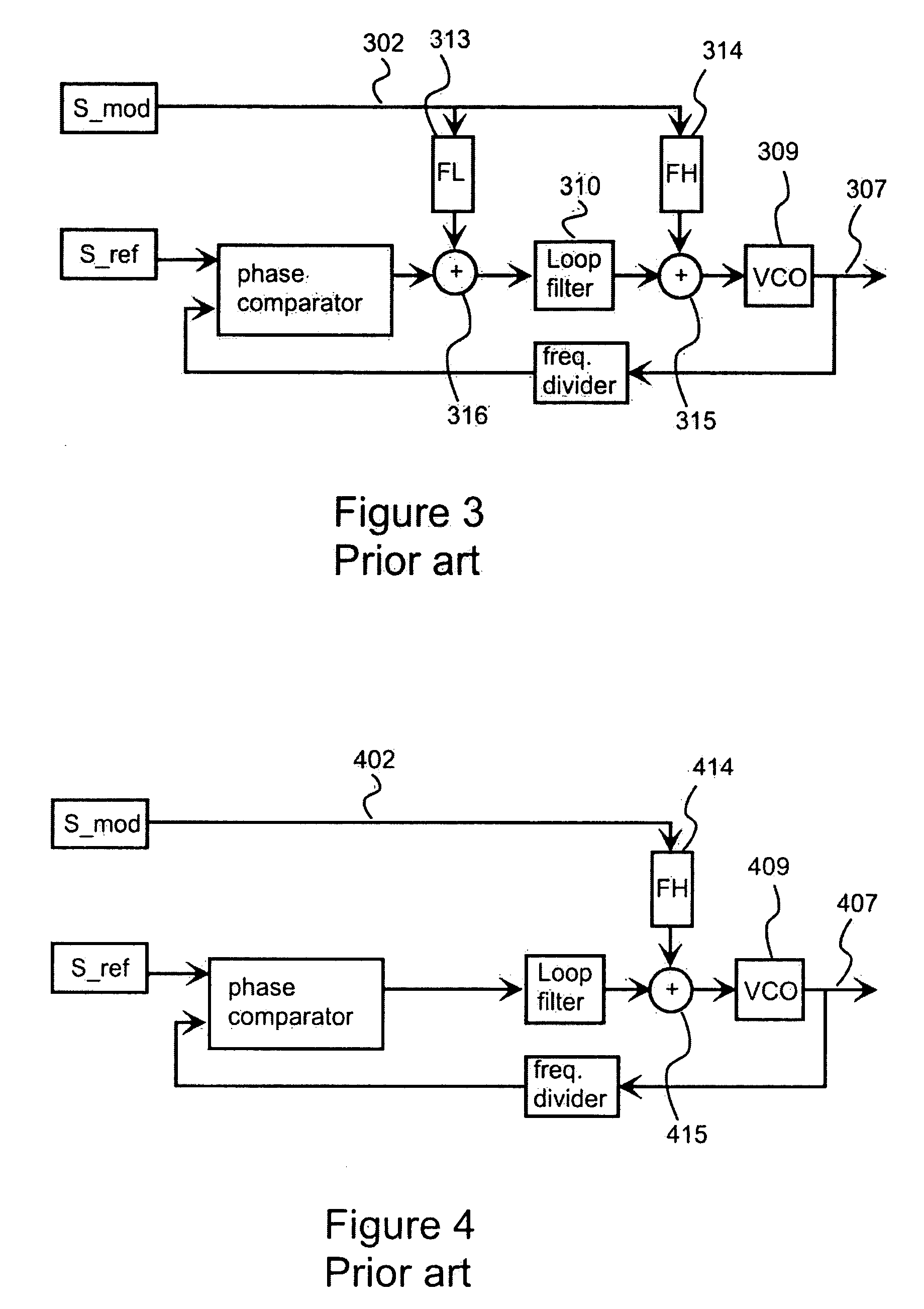
[0053]FIGS. 1-4 have been explained above in the description of the prior art.

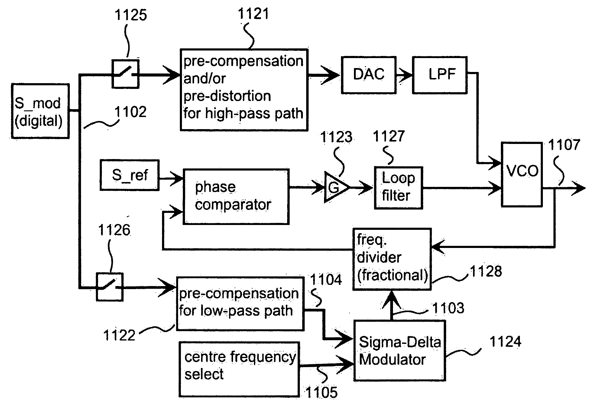
[0054]FIG. 5 shows a block diagram of a direct modulator according to an embodiment of the invention. A modulation signal 502 is presented in a digital form with a sufficient number of bits. The number of bits in a digital signal representation and in digital signal processing has to be so high, i.e. bit accuracy has to be so good, that quantization noise due to the fact that a digital representation can present only a finite number of values is on an acceptable level. A sample rate in digital signal processing has to be so high that even the highest frequency components of signals to be processed can be handled without aliasing effects. In FIG. 5, digital signals are presented with a bigger line width than analogue signals.

[0055] Digital modulation signal is filtered with a digital pre-compensation filter 521 that compensates a non-flat frequency response of a high-pass PLL transfer function. The digita...


PUM


Abstract

A radio frequency modulator based on direct frequency/phase modulation of output signal of a controllable oscillator (724) that is a part of a phase locked loop (PLL) provides a direct modulator that is able to operate over a wide frequency range with a flat frequency response. A modulation signal is digitally processed (721, 730) before injection to a high-pass path of a direct modulator. Applicability of digital signal processing is based on the fact that the modulation signal is a base band signal. Therefore, the modulation signal (702) occupies such a band in the frequency domain so that a sufficient ratio of a sampling rate to an upper edge frequency of the modulation signal can be achieved. Digital processing is used for compensating an effect of non-flat high-pass PLL transfer function and/or to perform pre-distortion of the input signal of a controlled oscillator to compensate an effect of non-linearity of a controlled oscillator.

Description

FIELD OF THE INVENTION [0001] The invention relates to radio frequency modulators. The invention especially concerns a radio frequency modulator based on direct modulation of an out-put signal of a controllable oscillator that is a part of a phase locked loop. BACKGROUND OF THE INVENTION [0002] Modulation can be defined as alteration of one or more characteristics of a certain waveform as a function of another signal that represents information. In radio frequency communication systems, a waveform the characteristics of which are altered is typically a sine wave. In this document a modulated sine wave is called a carrier and a signal that represent information is called a modulation signal. There are several methods for modulating a carrier, like linear amplitude modulation, frequency modulation, and phase modulation. In quadrature amplitude modulation (QAM) there are two sine waves being in a 90 degrees phase shift respect to each other. Each sine wave is modulated with amplitude m...

Claims


Application Information

Patent Timeline
IPC IPC(8): H04L25/03
CPCH03C3/0925H03C3/0933H03C3/0941H04L27/152H03C3/0958H03C3/0991H04L27/148H03C3/095
Inventor MATERO, JORMASHAKESHAFT, NIALL ERIC
Owner NOKIA TECHNOLOGLES OY
Why Eureka
Try Eureka