Plasma display panel having coplanar electrodes with constant width

a technology of coplanar electrodes and plasma panels, which is applied in the direction of gas discharge electrodes, gas discharge vessels/containers, gas-filled discharge tubes, etc., can solve the problems of reducing the luminous efficiency of the panel, and reducing the lifetime of the panel, so as to increase the luminous efficiency of the plasma panel and its lifetime

Inactive Publication Date: 2008-05-13
THOMSON LICENSING SA
View PDF11 Cites 0 Cited by
  • Summary
  • Abstract
  • Description
  • Claims
  • Application Information

AI Technical Summary

Benefits of technology

[0022]The object of the invention is to increase the luminous efficiency of plasma panels and their lifetime by avoiding these limitations and these drawbacks.

Problems solved by technology

The amplitude of these sustain pulses must be sufficient to cause discharges in those cells in the row that have been actuated beforehand but insufficient to cause discharges in the cells of this row that have not been activated beforehand.
This phenomenon results in bigger losses of the charged species on the barrier ribs and to accelerated deterioration of the phosphor material covering these barrier ribs with, as a consequence, a reduction in the luminous efficiency and a reduction in the lifetime of the panel.
However, at the end of expansion of the discharges, that is to say at the buses Yb of the coplanar electrodes, the same problem as previously is encountered since the electrodes extend at this point over the entire width of the cells.
The improvement in luminous efficiency and in lifetime therefore remains limited.
Furthermore, such a structure having electrode elements is more difficult to produce than that of FIGS. 1A and 1B and requires an expensive operation of horizontal alignment of the plates 11 and 12 so that the electrode elements specific to each cell are perfectly centered on each cell and equidistant from two adjacent column barrier ribs.

Method used


Image

  • Plasma display panel having coplanar electrodes with constant width
  • Plasma display panel having coplanar electrodes with constant width
  • Plasma display panel having coplanar electrodes with constant width

Examples


first embodiment

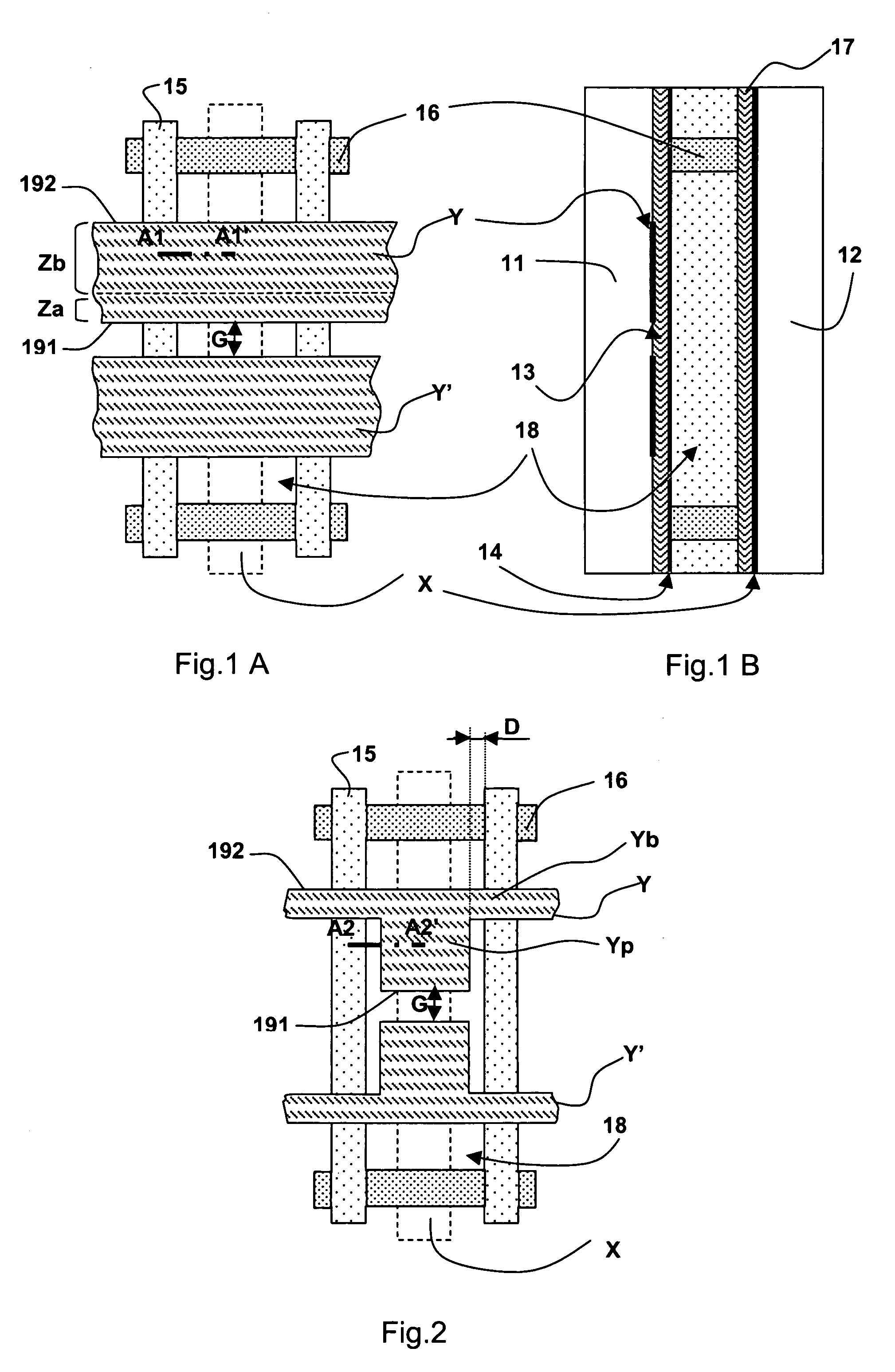
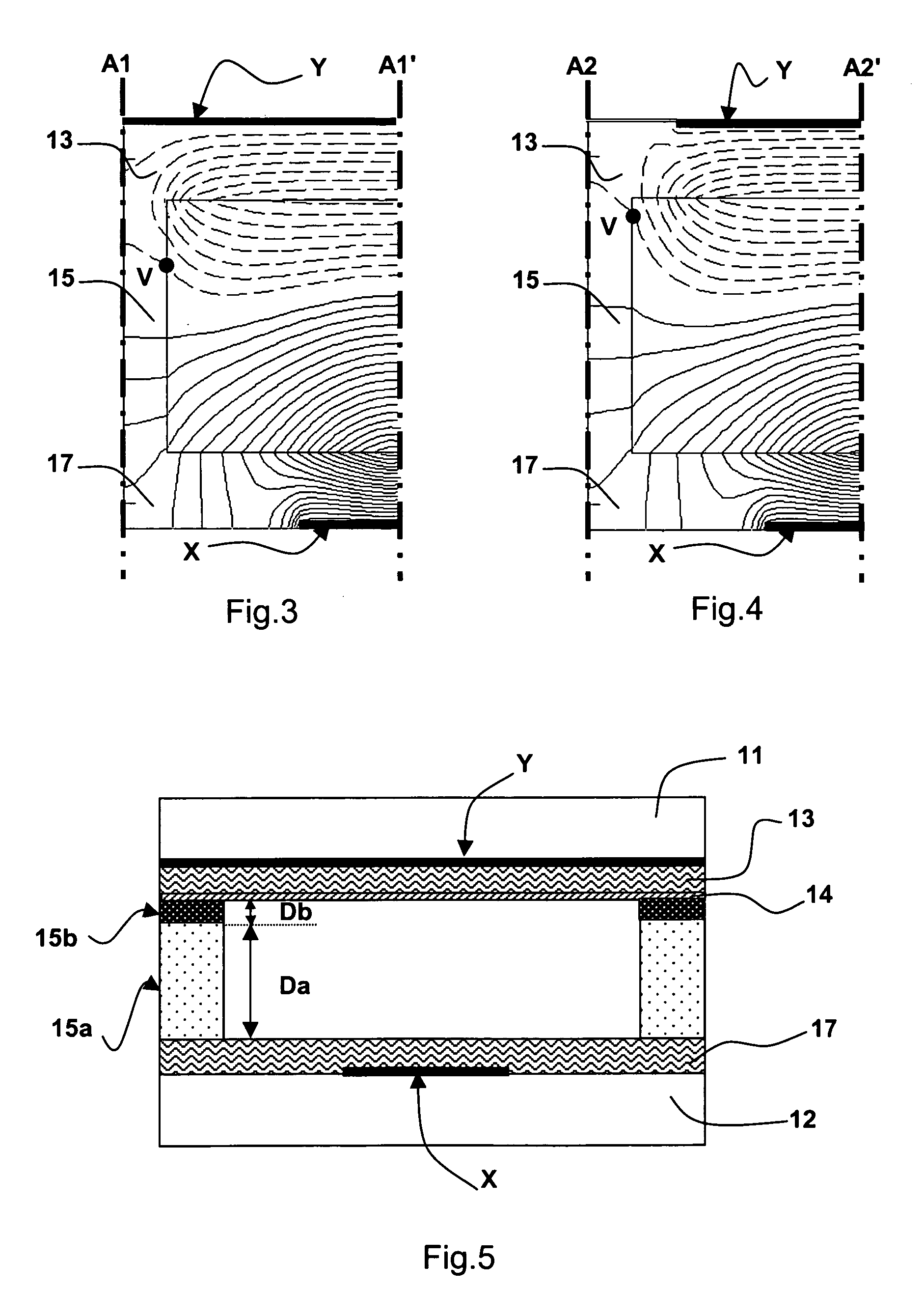
[0059]According to the invention shown in FIG. 5, the plasma panel includes the same elements arranged in the same structure as the panel of the prior art described with reference to FIGS. 1A and 1B, the only difference being that the column barrier ribs 15 include a base layer 15a in contact with the dielectric layer 17 covering the array of electrodes X of the second plate 12, and a continuous top layer 15b that is applied to the base layer 15a and extends as far as the dielectric layer 13 and the protective layer 14 covering the arrays of coplanar electrodes Y, Y′ of the first plate 11. Here, the coplanar electrodes each have a constant width over their entire useful length, and the electrode arrays are less expensive to produce and the operation of assembling the plates is not penalized by alignment constraints.

[0060]According to this embodiment, the thickness or height Da of the base layer and the mean dielectric permittivity Ea of its constituent material, on the one hand, and...

second embodiment

[0067]FIG. 8 illustrates, compared with FIG. 5, the invention in which the barrier ribs include a continuous upper layer 15c similar to the top layer 15b described above. This top layer 15c also has a low thickness Dc and a low permittivity Ec. This top layer 15c not only covers, as previously, the top of the barrier ribs but extends here, continuously over the entire active surface of the second plate 12. Such a configuration is advantageously easier to produce than that described above, for example using a screen-printing method for depositing said top layer. Taking Ea=5Ec and Da=5Dc and under the same conditions as previously, a surface potential distribution as shown in FIG. 9 is obtained. This figure shows that the discharge confinement effect obtained is quite comparable to that obtained with the embodiment described with reference to FIG. 7. By comparing FIGS. 7 and 9, it may be seen that replacing a top layer of the barrier ribs with a continuous upper layer coating the enti...

third embodiment

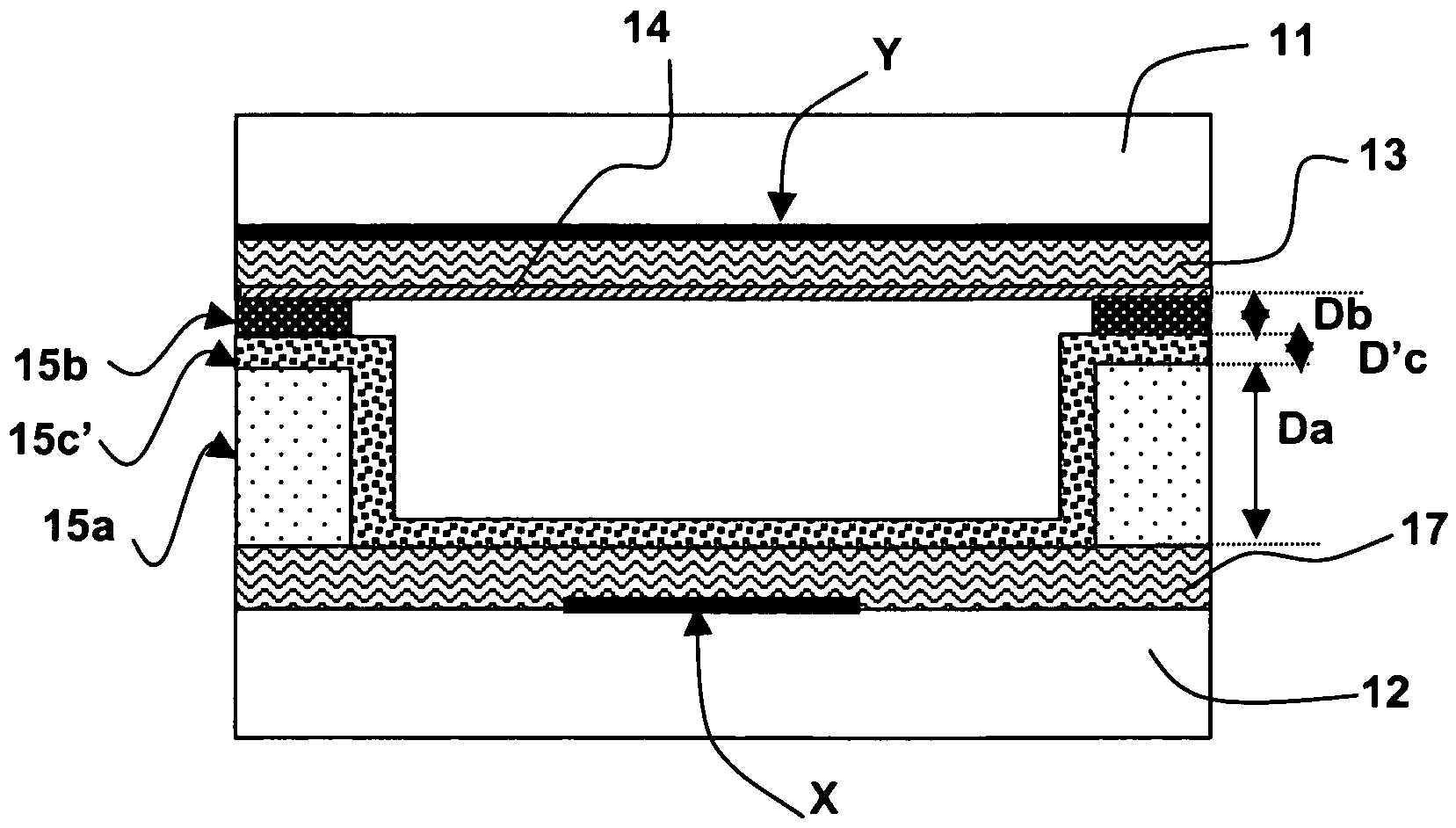
[0071]Furthermore according to this third embodiment, E′c>Ea>Eb and Da>D′c≧Db. Preferably, E′c>5Ea and Ea≧3Eb, with Da≧4D′c and D′c≧Db.

[0072]Apart from a low-permittivity region at the top of the barrier ribs, as in the first and second embodiments, is therefore here a high-permittivity region inserted between the base of the barrier ribs and this low-permittivity region.

[0073]In comparison with the first and second embodiments of the invention, the insertion, into the barrier ribs, of a high-permittivity intermediate region, namely the second layer 15c′, allows the equipotential lines in the barrier rib region corresponding to the first layer 15a and to the second layer 15c′ to be moved further apart, in such a way that the equipotential lines in the third layer 15b are even more closely spaced than previously, thereby improving the confinement of the discharges. Eb=Ea / 5, E′c=5Ea and Db=D′c=Da / 5, the distribution of the equipotential lines illustrated in FIG. 10, over the half-widt...


PUM


Abstract

Panel comprising an array of barrier ribs each having a base resting on a plate and a top in contact with another plate that includes at least two arrays of coplanar electrodes each preferably having a constant width. According to the invention, these barrier ribs have, at their top, a low-permittivity region of thickness greater than 3 μm and less than or equal to one fifth of their total height, which has a mean dielectric permittivity at least three times smaller than the dielectric permittivity of these barrier ribs measured at their base. Thanks to the invention, the confinement of the plasma discharges far from the barrier ribs is substantially improved.

Description

[0001]This application claims the benefit, under 35 U.S.C. §365 of International Application PCT / EP03 / 50639, filed Sep. 18, 2003, which was published in accordance with PCT Article 21(2) on Apr. 22, 2004 in French and which claims the benefit of French patent application No. 0212931, filed Sep. 27, 2002.BACKGROUND OF THE INVENTION [0002]The invention relates to a plasma display panel comprising, as shown in FIGS. 1A, 1B, a first plate 11 and a second plate 12 leaving between them a space filled with a discharge gas and compartmentalized into a number of discharge cells 18 arranged in rows and columns, which also includes an array of insulating barrier ribs comprising barrier ribs 15 each separating two adjacent columns of cells, the first plate including at least two arrays of coplanar electrodes Y, Y′ called sustain electrodes, which are oriented in general directions that are parallel to one another and perpendicular to said barrier ribs, having a constant width perpendicular to t...

Claims


Application Information

Patent Timeline
Patent Type & Authority Patents(United States)
IPC IPC(8): H01J17/49H01J11/12H01J11/36
CPCH01J11/12H01J11/36H01J2211/361H01J11/22H01J11/38
Inventor TESSIER, LAURENT
Owner THOMSON LICENSING SA
Why Eureka
Try Eureka