Abrasive water jet cutting machine

a cutting machine and water jet technology, applied in the direction of abrasive blasting machines, abrasive apparatus, manufacturing tools, etc., can solve the problems of large amount of unconsumed abrasives being disposed, workpieces being cut, and production efficiency being significantly reduced, so as to improve the cutting quality of workpieces

Inactive Publication Date: 2007-02-15
DISCO CORP
View PDF3 Cites 19 Cited by
  • Summary
  • Abstract
  • Description
  • Claims
  • Application Information

AI Technical Summary

Benefits of technology

[0013] It is an object to provide a new and improved abrasive water jet cutting machine, in which an abrasive recovery unit can be continuously used without needing maintenance, and an abrasive having uniform grain size can be easily recovered.
[0015] According to such an abrasive sorting tank, the abrasive having the grain size in the reusable predetermined range can be sorted and recovered without using the abrasive recovery filter. Therefore, the abrasive recovery unit can be continuously used over a long period without needing maintenance of the abrasive recovery unit. Moreover, according to the abrasive sorting tank, since the abrasive is accurately sorted and thus uniform abrasive is easily obtained compared with a case of using the abrasive recovery filter, cutting quality of workpiece can be improved.
[0016] Height of each of the first and second sorting members may be changed. Thus, height of the first sorting member is changed, thereby maximal grain size of the abrasive to be recovered for reuse can be changed, and height of the second sorting member is changed, thereby minimal grain size of the abrasive to be recovered for reuse can be changed.
[0018] As described hereinbefore, according to the present invention, since the abrasive recovery filter is not used, the abrasive recovery unit can be continuously used over a long period without needing maintenance of the abrasive recovery unit. Moreover, since the uniform abrasive is easily obtained compared with the case of using the abrasive recovery filter, cutting quality of workpiece can be improved.

Problems solved by technology

The abrasive collides with the workpiece at high speed with the high-pressure water so that the workpiece is cut while being partially broken.
This is because all abrasive jetted with the high-pressure water from a jet nozzle is not consumed to contribute to the process in one time of cutting of the workpiece, therefore if the abrasive is disposable, a large amount of unconsumed abrasive is disposed, consequently production efficiency is significantly reduced.
This is because abrasive having excessively small grain size can not contribute to polishing even if it is reused, and on the other hand, abrasive having excessively large grain size may cause dogging of the jet nozzle 130.
However, in the abrasive recovery apparatus 160, there has been a difficulty that since the abrasive recovery filter 167 is disposed in a firmly sealed housing, it is extremely difficult for an operator to replace the abrasive recovery filter 167.
It is considered to be one reason for this that since a minimum of the grain size is controlled by flow velocity of the water stream, the minimum is extremely unstable.
There has been a further difficulty that the amount of the abrasive that is discharged in this way despite being reusable is estimated to reach about 8% of the total amount of reusable abrasive, thereby productivity is significantly reduced.
However, if the quality is intended to be realized in the abrasive recovery apparatus 160, it is necessary that the flow velocity of the abrasive mixture liquid flowing on the abrasive recovery filter 167 is increased, and the meshes of the abrasive recovery filter are reduced, consequently a ratio of the reusable abrasive that can not be recovered is further increased, therefore it is extremely difficult to make the grain size of the abrasive uniform.

Method used


Image

  • Abrasive water jet cutting machine
  • Abrasive water jet cutting machine
  • Abrasive water jet cutting machine

Examples


first embodiment

[0025] Hereinafter, an abrasive water jet cutting machine according to a first embodiment of the invention is described. While the abrasive water jet cutting machine according to the embodiment is configured as, for example, a water jet cutting machine for cutting workpiece by a jet stream of high-pressure water mixed with the abrasive (abrasive jet) as described below, the invention is not limited to such an example.

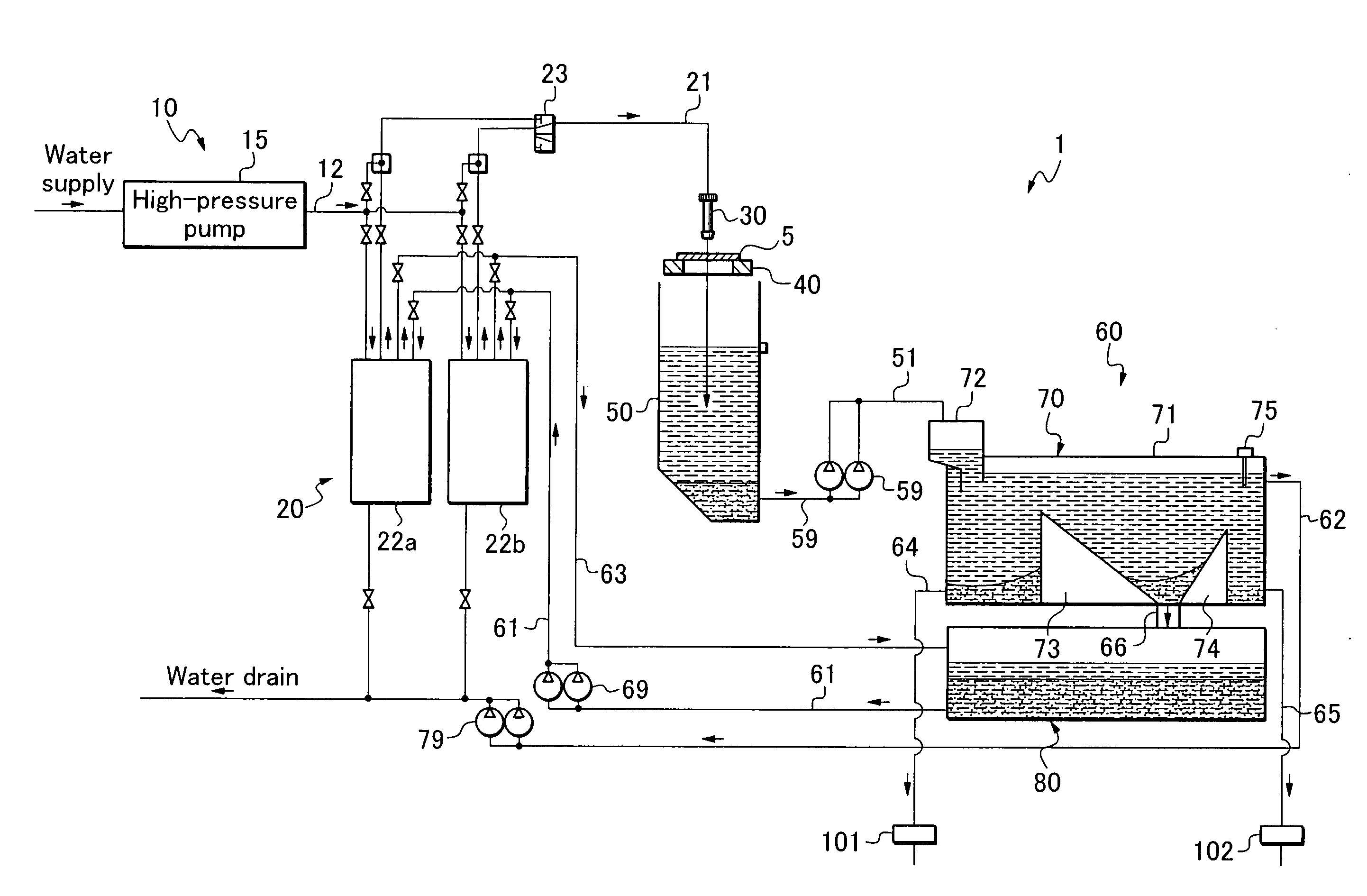
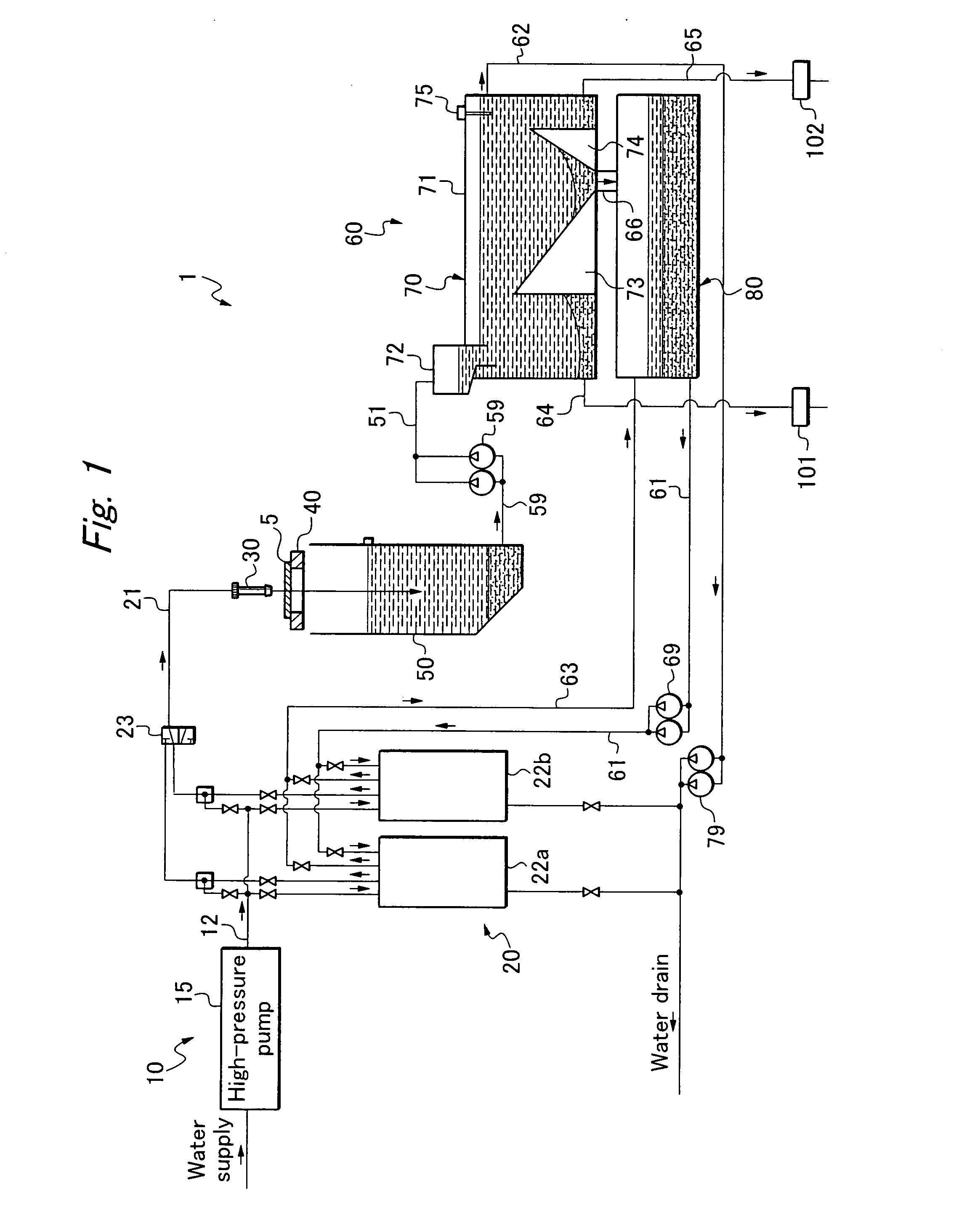
[0026] First, a general configuration of a water jet cutting machine 1 according to the embodiment is described according to FIG. 1. FIG. 1 is an explanatory view showing a general configuration of the water jet cutting machine 1 according to the embodiment.

[0027] As shown in FIG. 1, the water jet cutting machine 1 according to the embodiment is a cutting machine that can perform an accurate cutting process (that is, water jet process) to workpiece 5 at a comparatively free cutting line by jetting high-pressure water including abrasive. While the workpiece 5 as a cutt...


PUM

PropertyMeasurementUnit
grain sizeaaaaaaaaaa
sizeaaaaaaaaaa

Abstract

To provide an abrasive water jet cutting machine in which an abrasive recovery unit can be continuously used without needing maintenance, and an abrasive having a uniform grain size can be easily recovered, the machine has a catch tank for receiving a high-pressure abrasive mixture liquid jetted from a jet nozzle, and an abrasive recovery unit that recovers abrasive having a grain size in a reusable predetermined range from the abrasive mixture liquid transported from the catch tank, and transports abrasive mixture liquid including recovered abrasive into an abrasive-mixture-liquid retention tank; wherein the abrasive recovery unit has an abrasive sorting tank which flows the abrasive mixture liquid transported from the catch tank in an approximately horizontal direction, and sorts abrasive depending on grain size by using difference in sedimentation rate depending on grain size, and recovers the abrasive having the grain size in the reusable predetermined range.

Description

BACKGROUND OF THE INVENTION [0001] 1. Field of the Invention [0002] The present invention relates to an abrasive water jet cutting machine for cutting workpiece by jetting a high-pressure liquid including abrasive. [0003] 2. Related Art [0004] A water jet is a jet stream of high-pressure water formed by providing energy to water by a super high-pressure pump and the like, and for example, has flow velocity one to three times faster than the sound velocity. In these years, methods and machines for cutting various kinds of workpiece by using the water jet have been developed. In particular, an abrasive jet is now noticed in order to improve a cutting efficiency, in which solid abrasive is mixed in high-pressure water. The abrasive includes a material having high hardness such as gamet, alumina, and silicon carbide, which has a granular body having a grain size of, for example, about several ten to several hundred micrometers. The abrasive collides with the workpiece at high speed with...

Claims


Application Information

Patent Timeline
Patent Type & Authority Applications(United States)
IPC IPC(8): B24C3/00
CPCB24C9/006B24C1/045Y02P70/10
Inventor MATSUBARA, MASAYUKITATEIWA, SATOSHIKANAI, SHIGEKAZUYAMAMOTO, MASAAKI
Owner DISCO CORP
Why Eureka
Try Eureka