[0017] It is an object of the present invention to simultaneously ensure the strength of an inner member and the dimensional accuracy of a female spline portion of a shaft hole of the inner member in the case where the female spline portion is subjected to heat treatment and to suppress the backlash of spline fit with a shaft.
[0020] Desirably, the hardened layer is formed by heat treatment by means of induction
quenching. The heat treatment by means of induction
quenching is preferable since a hardened layer having a large depth can be easily formed in order to enhance the strength of the inner member and since in-line
processing can be achieved for a
production line. Furthermore, the female spline portion, an outside
diameter surface which is to be brought into contact with the inner diameter surface of a
retainer, and track grooves for allowing a ball to roll can be subjected to the heat treatment at the same time in one step. Therefore, productivity is superior, resulting in a cost
advantage. Moreover, the
interference fit of the shaft with respect to the inner ring can be adjusted through the case depth in the hardened layer. Here, the hardened layer can be formed discontinuously along a circumferential direction of the shaft hole. Alternatively, it can be formed over the entire circumference.
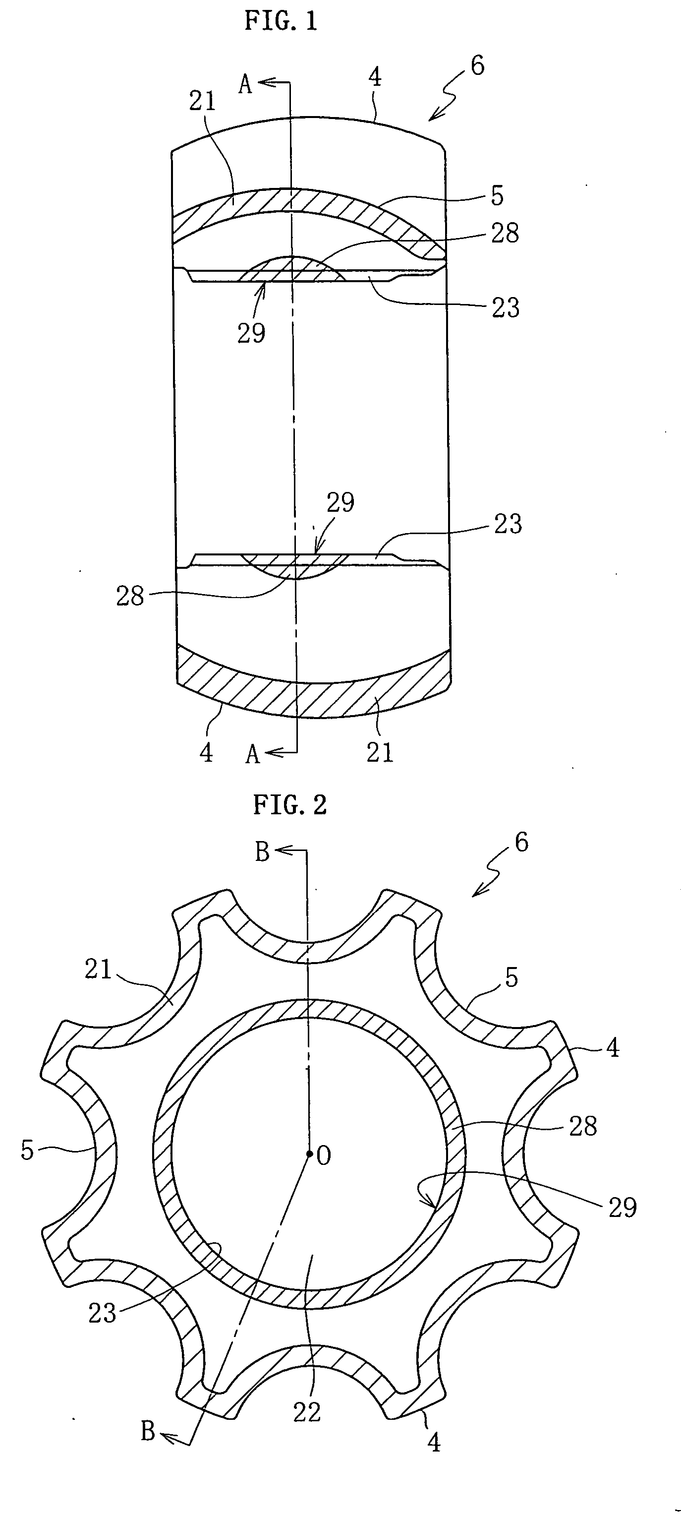
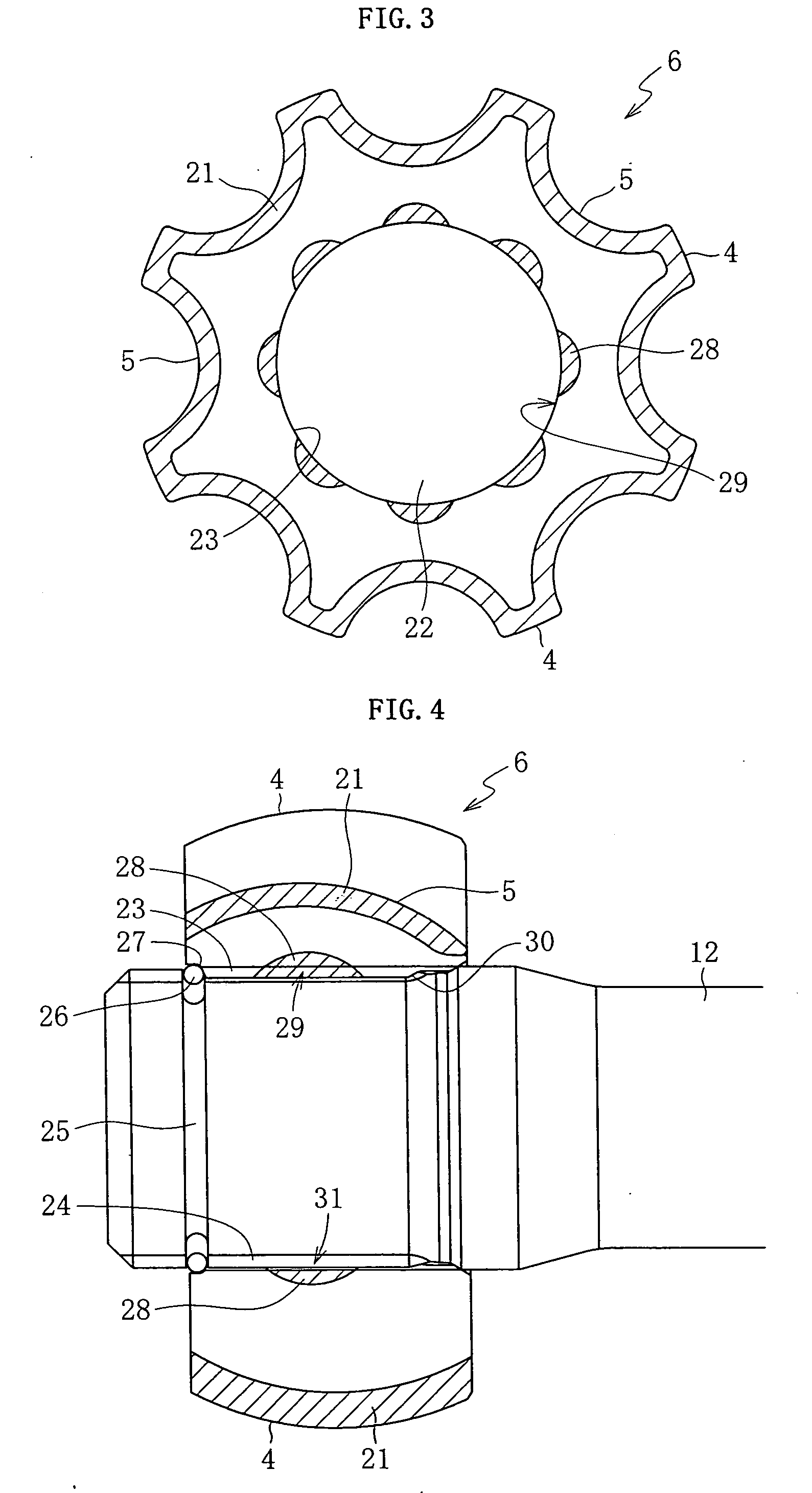
[0024] Accordingly, in the present invention, the hardened layer by means of heat treatment is formed only in the axial central portion of the shaft hole of the inner member. By subjecting only the axial central portion of the shaft hole to the heat treatment, martensitic transformation induced by the heat treatment occurs in the inner diameter portion of the axial central portion, and the volume thereof is expanded to cause the inner diameter at the female spline portion to decrease. Here, the both axial side portions other than the axial central portion remain as a non-
heat treated portion. As described above, only part of the female spline portion is subjected to heat treatment, and the rest remains as a non-
heat treated portion. Therefore, the dimensional accuracy of the female spline portion can be ensured.
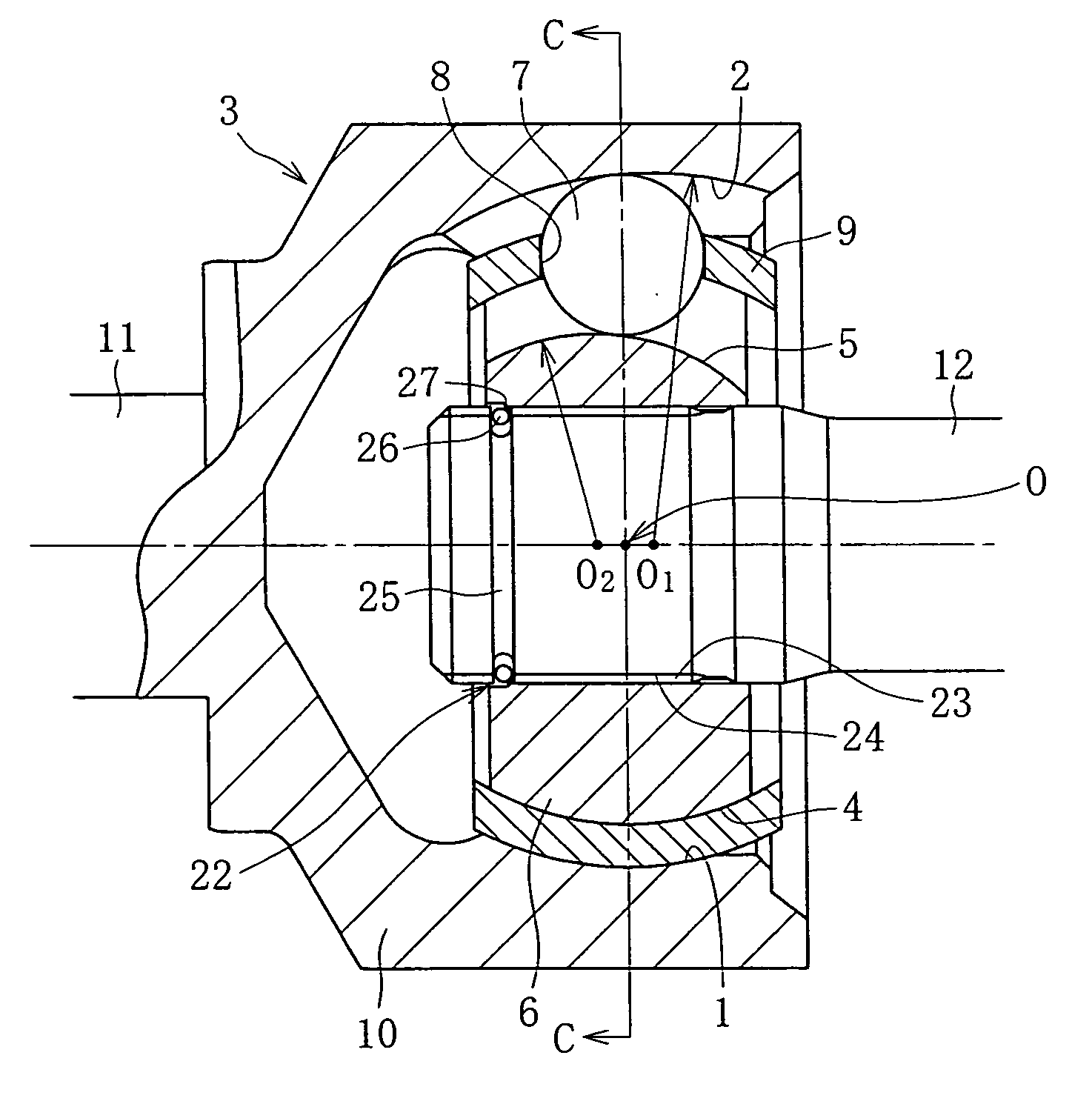
[0025] In the structure in which the inner member is spline-fitted into the shaft, the shaft is press-fitted to the inner member in the axial central portion of the female spline portion which central portion has a smaller inner diameter. In the conventional case, when twist torque is applied to the shaft, stress is concentrated on the spline base portion of the shaft which portion serves as a fulcrum for the twist. However, in the present invention, as a consequence of the press-fit, stress is also concentrated on the axial central portion of the female spline portions in the press-fitted state. Therefore, the
stress concentration on the spline base portion of the shaft can be dispersed and relaxed.
[0026] Normally, the inner member has a shape having a spherical outside diameter surface, i.e., a shape in which the axial central portion has a large thickness and the both axial side portions have a small thickness. In the conventional case, the stress is concentrated on the spline base portion of the shaft, which portion corresponds to one of the axial side portions having a small thickness. However, in the present invention, since the axial central portion on which the stress is concentrated has the largest thickness, the strength of the inner member can be ensured.
[0027] In addition, since the inner diameter is small in the axial central portion of the female spline portion of the inner member, the shaft and the inner member are brought to a press-fitted state in the axial central portion of the inner member. Therefore, the backlash can be eliminated in the spline fit between the inner member and the shaft without additionally providing a twist angle to the shaft.

