
Auto-calibration algorithm with hysteresis correction

a technology of auto-calibration and correction algorithm, which is applied in the calibration/testing of force/torque/work measurement apparatus, instruments, liquid/fluent solid measurement, etc., can solve the problems of reducing sensor reliability and accuracy, non-zero sensitivity of sensor, and sensor accuracy reduction, etc., to improve the accuracy of force sensor assembly and magnetometer.

Inactive Publication Date: 2007-02-15
SIEMENS VDO AUTOMOTIVE CORP
View PDF21 Cites 11 Cited by
  • Summary
  • Abstract
  • Description
  • Claims
  • Application Information

AI Technical Summary

Benefits of technology

[0012] Accordingly, the method according to this invention provides for improved accuracy of a force sensor assembly and magnetometer.

Problems solved by technology

Disadvantageously, although the individual magnetometer sections are produced to the same specifications, some differences occur and therefore can cause an asymmetrical sensitivity of the magnetic sense elements allowing non-zero sensitivity of the sensor to non-divergent magnetic fields.
Such a phenomenon reduces the reliability and accuracy of the sensor.
Further, hysteresis present within the magnetoelastic element may also prevent the transducer from returning to an original zero point after the application and subsequent removal of a force stimulus, also disrupting and reducing sensor accuracy.

Method used


Image

  • Auto-calibration algorithm with hysteresis correction
  • Auto-calibration algorithm with hysteresis correction
  • Auto-calibration algorithm with hysteresis correction

Examples


Embodiment Construction

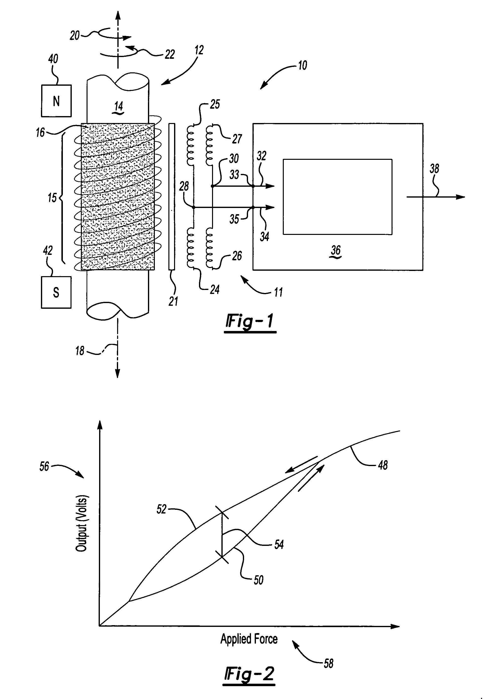
[0017] Referring to FIG. 1, a torque sensor assembly 10 is schematically shown and includes a torque transducer 12 disposed about an axis 18. The torque transducer 12 includes a shaft 14 with a magnetoelastic ring 16. The magnetoelastic ring 16 produces a magnetic field 15 responsive to the application of torque on the shaft 14. A magnetometer assembly 11 includes an inductor 21 disposed adjacent the torque transducer 12 that is magnetically saturated by a coil assembly. The coil assembly includes upper inner and outer coils 25, 27 and lower inner and outer coils 24, 26. The inner coils 25, 24 are configured to generate a magnetic field equal and opposite to a magnetic field generated by the outer coils 26, 27.

[0018] A controller 36 energizes the coils 24, 25, 26, 27 with an alternating current to generate an alternating magnetic field. The alternating magnetic field causes a magnetic saturation of the inductor 21. When a torque is applied to the torque transducer 12, the generated...


PUM


Abstract

A method of calibrating a magnetoelastic force sensor includes the steps of mating a force transducer with a magnetometer, applying a force to the force transducer at each of a plurality of defined calibration points, recording output signals indicative of a magnetic field generated at each of the defined calibration points communicated to each of the at least two channels, and determining a correction factor for each of the at least two channels based on the recorded output signals for each of the defined calibration points.

Description

CROSS REFERENCE TO RELATED APPLICATION [0001] The application claims priority to U.S. Provisional Application No. 60 / 708,063, which was filed on Aug. 12, 2005.BACKGROUND OF THE INVENTION [0002] This invention generally relates to a method of calibrating a magnetometer for a force sensor. More particularly, this invention relates to a method of calibrating a magnetometer for a force sensor for decreasing variability. [0003] A type of force sensor includes a transducer element that includes a magnetoelastic material containing two adjacent, oppositely circumferentially magnetically polarized axial regions, that each produces a magnetic field responsive to an applied force. This magnetic field is divergent in nature, for detection by a magnetometer circuit configured as a magnetic gradiometer. The generated magnetic field is then detected by the magnetometer that provides an output signal indicative of an applied force, and provides a minimal sensitivity to non-divergent extraneous mag...

Claims


Application Information

Patent Timeline
Patent Type & Authority Applications(United States)
IPC IPC(8): G01D18/00
CPCG01L25/003G01L3/102G01L3/105
Inventor CRIPE, DAVID W.
Owner SIEMENS VDO AUTOMOTIVE CORP
Learn More