Hydrogen Energy Systems

a technology of energy systems and hydrogen fuel, applied in the direction of electrolysis components, aluminium compounds, electrolysis processes, etc., can solve the problems of no system that efficiently, safely and easily generates hydrogen, no system exists that provides safe and simple modification of gasoline or diesel internal combustion engines to run partially on hydrogen fuel, no system exists that efficiently, safely and easily provides heated water, etc., to achieve the effect of preventing overheating

Inactive Publication Date: 2007-02-22
BARTEL BRIAN G
View PDF15 Cites 52 Cited by
  • Summary
  • Abstract
  • Description
  • Claims
  • Application Information

AI Technical Summary

Benefits of technology

[0013] In accordance with a preferred embodiment hereof, this invention provides a galvanic hydrogen generator system, relating to generating hydrogen gas from water, comprising: at least one galvanic cell, comprising at least one anode; at least one cathode; and at least one buffer having an electrochemical potential between such at least one anode and such at least one cathode; at least one container, adapted to contain such at least one galvanic cell, comprising volume in excess of five gallons, at least one construction seam, at least one hydrogen gas storage headspace, and at least one hydrogen gas release valve; wherein such at least one construction seam is substantially permanently sealed; wherein such at least one anode initially weighs at least about seven pounds; and wherein such at least one container is adapted to hold at least one quantity of water sufficient (relative to the quantity of such at least one anode) to prevent overheating resulting in passivation of such at least one anode.

Problems solved by technology

No system exists that efficiently, safely, and easily generates hydrogen gas from water for use as fuel without the need to supply electrical power from outside the hydrogen generator.
Further, no system exists that provides safe and simple modification of gasoline or diesel-powered internal combustion engines to run partially on hydrogen fuel.
No system exists that efficiently, safely, and easily provides heated water and hydrogen for hot-water using appliances.

Method used


Image

  • Hydrogen Energy Systems
  • Hydrogen Energy Systems
  • Hydrogen Energy Systems

Examples


Embodiment Construction

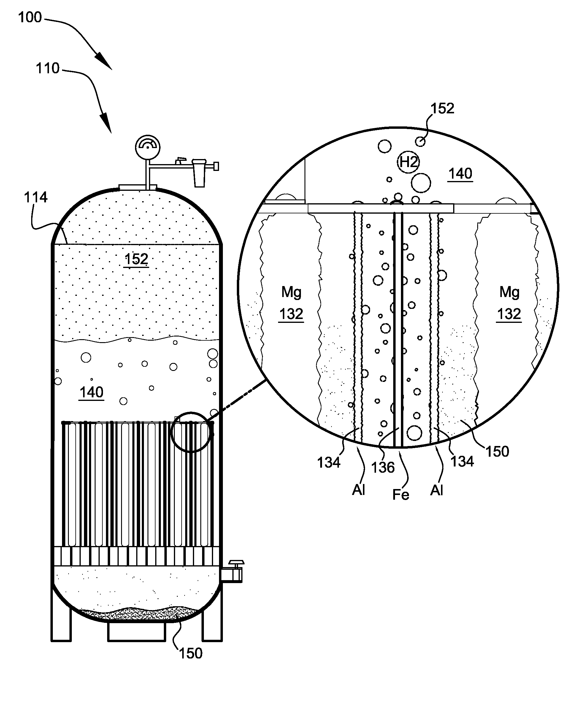
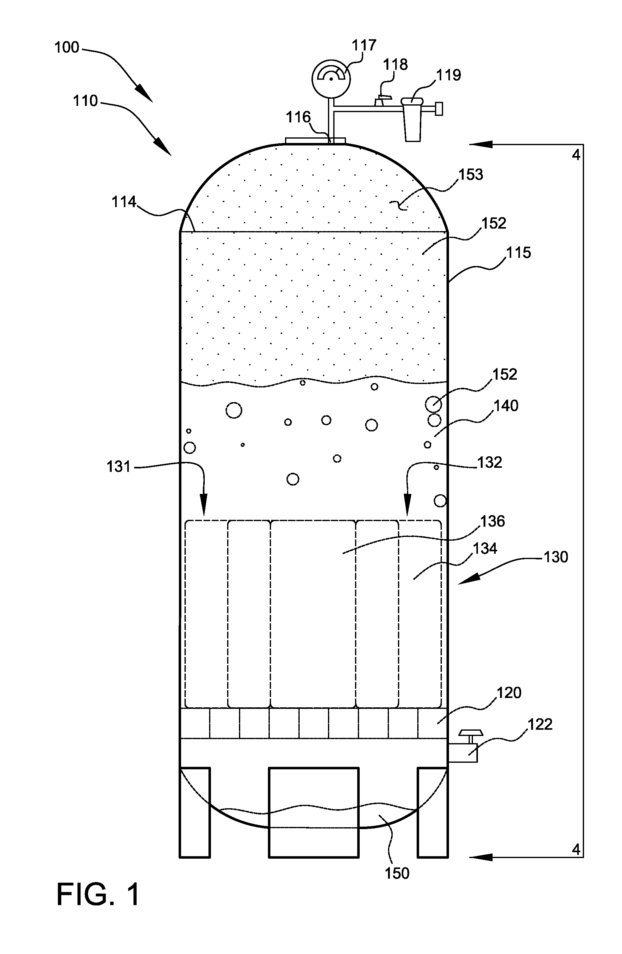
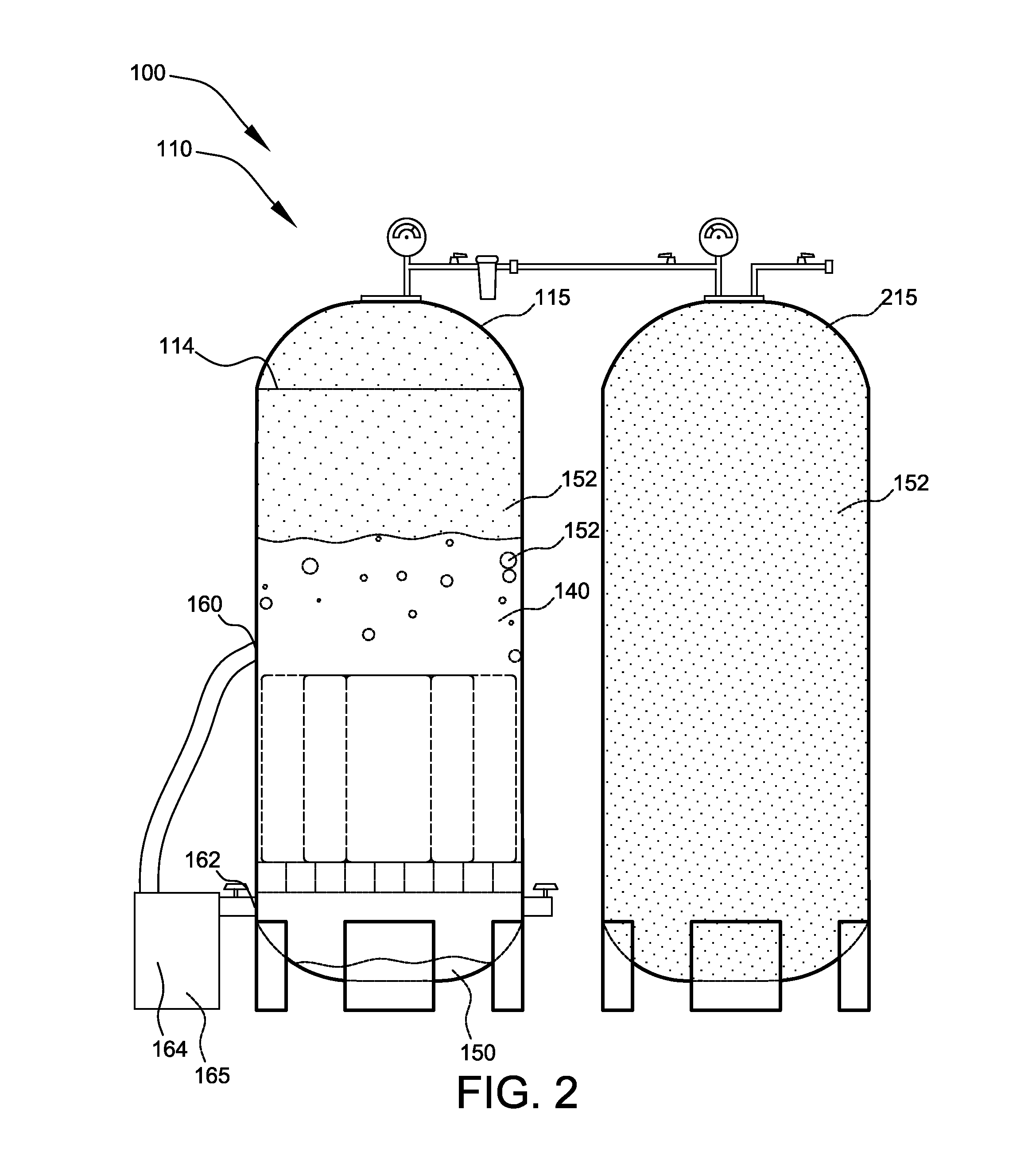
[0085]FIG. 1 shows a side view illustrating large galvanic hydrogen generator 110 according to a preferred embodiment of the present invention. Preferably, hydrogen energy system 100 comprises large galvanic hydrogen generator 110, as shown. Preferably, large galvanic hydrogen generator 110 comprises a container, preferably tank 115, and galvanic cell 130, as shown.

[0086] Preferably, tank 115 comprises a gas-tight tank, preferably a stainless steel tank, preferably a 99-gallon gas tank (preferably a propane tank that has been temporarily opened to receive galvanic cell 130 and then has been sealed shut again along construction seam 114), as shown. Preferably, tank 115 comprises gas outlet 116, pressure gauge 117, valve 118, filter 119, and support 120, as shown. Preferably, tank 115 further comprises water outlet 122, as shown. Preferably, filter 119 removes water vapor from hydrogen gas 152. Upon reading the teachings of this specification, those with ordinary skill in the art wil...


PUM

PropertyMeasurementUnit
volumeaaaaaaaaaa
pressuresaaaaaaaaaa
pHaaaaaaaaaa

Abstract

A hydrogen energy system comprising galvanic hydrogen generators and hydrogen input manifolds for vehicle engines. The galvanic hydrogen generators generate hydrogen gas, magnesium hydroxide, and heat by the galvanic reaction of magnesium anodes with steel cathodes in salt water. Heat exchangers channel excess heat to a heat sink such as a thermocouple, Stirling engine, hot water system, etc. The hydrogen input manifold is bolted between the engine block and the air intake manifold of a gasoline or diesel engine. Hydrogen gas is injected into the hydrogen input manifold to provide supplementary fuel to the engine, lowering the amount of petroleum that is used.

Description

CROSS-REFERENCE TO RELATED APPLICATIONS [0001] The present application is related to and claims priority from prior provisional application Ser. No. 60 / 710,538, filed Aug. 22, 2005, entitled “Hydrogen Energy Systems”, and is related to and claims priority from prior provisional application Ser. No. 60 / 745,056, filed Apr. 18, 2006, entitled “Hydrogen Energy Systems”, the contents of both of which are incorporated herein by this reference and are not admitted to be prior art with respect to the present invention by the mention in this cross-reference section.BACKGROUND [0002] The present invention relates to hydrogen energy systems. More particularly, the present invention relates to efficient galvanic hydrogen generation. Even more particularly, the present invention relates to hydrogen-fueled internal combustion engines. [0003] No system exists that efficiently, safely, and easily generates hydrogen gas from water for use as fuel without the need to supply electrical power from outs...

Claims


Application Information

Patent Timeline
Patent Type & Authority Applications(United States)
IPC IPC(8): C25B9/00
CPCC01B3/08C01F5/14C25B5/00Y02E60/36C01F7/428
Inventor BARTEL, BRIAN G.
Owner BARTEL BRIAN G
Why Eureka
Try Eureka