
Process for anodizing a robotic device

a robotic device and process technology, applied in the field of robotics, can solve the problems of limiting the number of previous robotic hands, limiting the practicality of all but the simplest previous robotic hands, and not contributing significantly to the economy and society

Inactive Publication Date: 2007-02-22
BARRETT TECH LLC
View PDF8 Cites 14 Cited by
  • Summary
  • Abstract
  • Description
  • Claims
  • Application Information

AI Technical Summary

Benefits of technology

The invention is a self-contained, practical robotic device that can manipulate objects. It has a base and at least one finger with two degrees of freedom connected in series at a rotary joint. The device has actuators and sensors to monitor its operating parameters. It is powered and controlled by a network operating controller that coordinates the operation of the robotic hand. The device is also sealed, immersible, and has electrical connections through the rotary joints for anodizing. The invention includes a process for anodizing the device without premasking. The technical effects of the invention are that it is practical, self-contained, and has the ability to manipulate objects with precision.

Problems solved by technology

Robotics, however, at present does not contribute significantly to the economy and society.
Industrial robots spend their entire lives repeating steps like these, making them expensive alternatives for the equally effective dedicated machinery that they replace.
Rather, market forces drive this split.
The restriction on practicality excludes all but the simplest previous robotic hands that, while otherwise sophisticated or dexterous, were never intended for practical use on a commercial robotic arm.
Design problems are increased, and durability (“robustness”) is seriously adversely affected.
Also, a prototype dexterous hand is rendered impractical when its electronics and drive components are too bulky, requiring an increase in the height of the hand.
The distance from the wrist center to the payload center, which is directly dependent on the hand height, degrades overall system performance in two ways.
First, it reduces available torque at the robot joints, especially for the wrist, for any given payload.
Second, it limits the size of the dexterous workspace, so that simple wrist rotations increasingly require increasingly exaggerated motions of the biggest, heaviest arm links.
The greater this motion, the more joint-drive-power required, the more effort required to avoid collisions, and the lower the margin of safety.
The slenderness is limited by the complex joints which must both support loads with bearing sets and impart torques with mechanical drives.
Electrical wires can be routed on the outside of a robot by users, but with huge cost, because the robot ends up wrapping and unwrapping the wires around the structure as the joints rotate.
Furthermore, to reduce fatigue, expensive cable (“robot cable”) is installed with generous (volume-expensive coils) at each joint axis.
The need to reserve free space at each joint axis for coils of wire, impacts the cost of the joint mechanisms severely, arguably creating the greatest single cost and performance impact on any robot, whether arm or hand.
They also cannot accommodate more than a couple air hoses or wires.
While some researchers claim that their hands can be commercially viable, the usual suggestions are not in fact practical.
However, the industry firmly rejects removing the forearm and wrist.
The tether restriction limits the amount of sensor or control bandwidth that can be supported between the arm base and the tool.
While the robotic transport mechanism is far bigger and more expensive than the tool, its only role is transportation of the tool.
Otherwise the arm's own bulk obstructs valuable workspace, blocks access to the work piece, and introduces the dominant safety hazard.
In general, the more complex the task(s), the greater the reliance on both tool variety and sensor input.
But grippers have no control or sensing, so their action runs full speed into mechanical stops on every cycle, concentrating failure there.
Another disadvantage for dexterous hands generally—as compared to grippers with pre-shaped gripper-jaw geometries—that goes counter to conventional wisdom is that dexterity does not provide position information to the same level as gripper jaws with limited motion and geometric locating features formed on the jaws of the grippers.
Errors in robot trajectories during programming and misplaced payloads after programming are the usual culprits.
These considerations have also deterred the adoption of dexterous hands for commercial applications.
In short, known dexterous hands are not practical.

Method used


Image

  • Process for anodizing a robotic device
  • Process for anodizing a robotic device
  • Process for anodizing a robotic device

Examples


Embodiment Construction

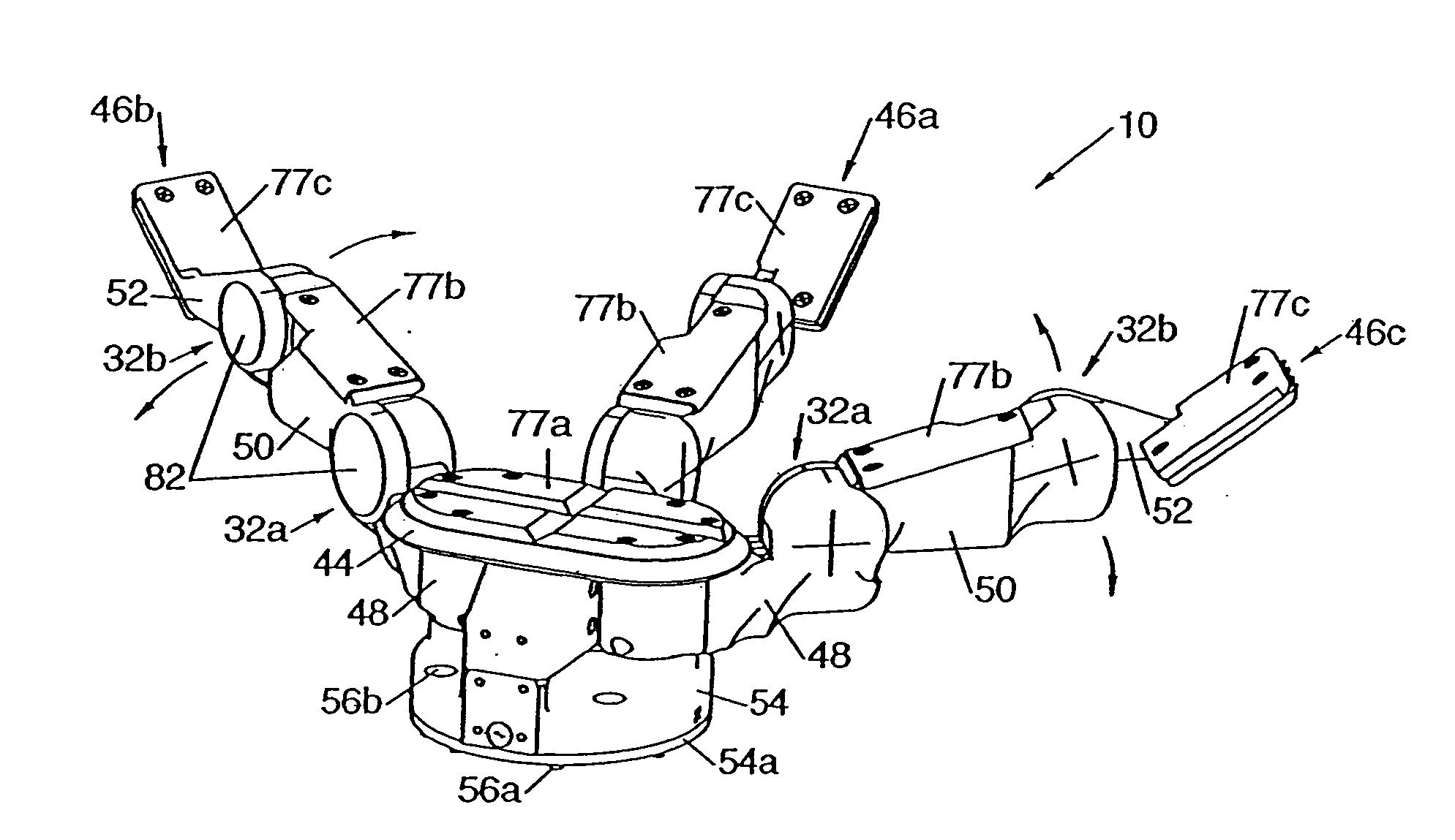
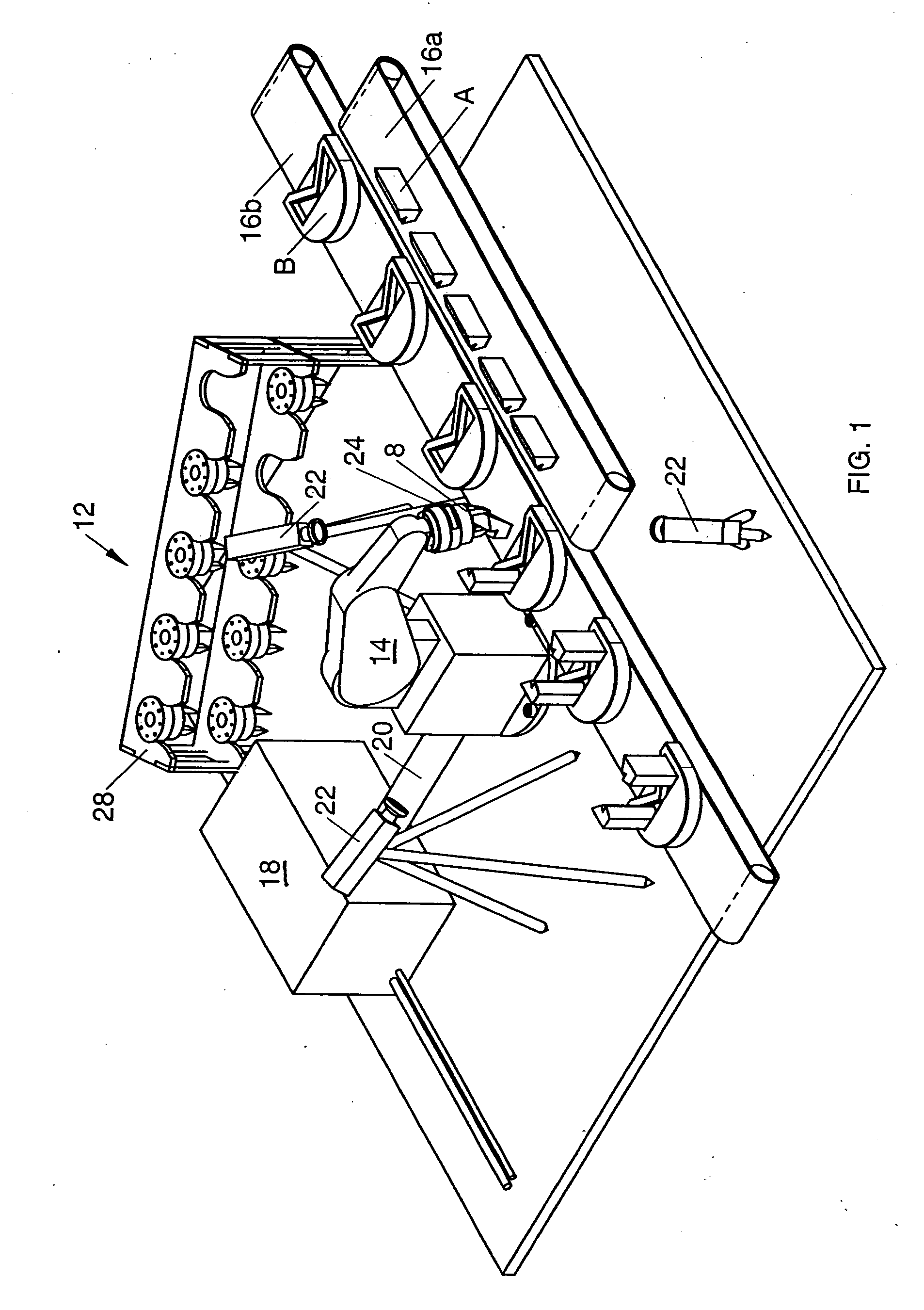
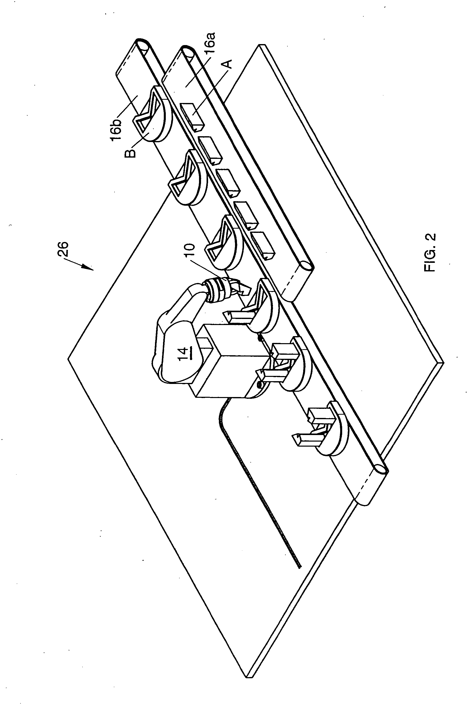
[0069] In existing practical robotic systems such as the workcell shown in FIG. 1, the intelligence and dexterity are concentrated around the static workcell area 12 and on the robotic arm 14 or other moving platform that supports a prior art tool 8, but never at the tool itself. While several intelligent and dexterous research-prototype robotic hands have been built in order to emulate human hand motion or to study the mathematics of multi-fingered manipulation, these devices are not designed to make a complete system more useful for completing practical tasks. For example, in order to design such a hand, either the hand is not compact or the sizable electronics are located outside the hand. As a result, applicants are not aware of any being used in a commercial application.

[0070] The tool 8, which comes in direct contact with the task, here the assembly of parts A transported on conveyor 16A to one of parts B transported on conveyor 16B moving in the opposite direction, is merely...


PUM

PropertyMeasurementUnit
voltagesaaaaaaaaaa
voltagesaaaaaaaaaa
voltagesaaaaaaaaaa

Abstract

A robotic device has a base and at least one finger having at least two links that are connected in series on rotary joints with at least two degrees of freedom. A brushless motor and an associated controller are located at each joint to produce a rotational movement of a link. Wires for electrical power and communication serially connect the controllers in a distributed control network. A network operating controller coordinates the operation of the network, including power distribution. At least one, but more typically two to five, wires interconnect all the controllers through one or more joints. Motor sensors and external world sensors monitor operating parameters of the robotic hand. The electrical signal output of the sensors can be input anywhere on the distributed control network. V-grooves on the robotic hand locate objects precisely and assist in gripping. The hand is sealed, immersible and has electrical connections through the rotary joints for anodizing in a single dunk without masking. In various forms, this intelligent, self-contained, dexterous hand, or combinations of such hands, can perform a wide variety of object gripping and manipulating tasks, as well as locomotion and combinations of locomotion and gripping.

Description

CROSS REFERENCE TO RELATED APPLICATIONS [0001] This application claims the benefit of U.S. provisional application No. 60 / 414,044 filed on Sep. 26, 2.002.GOVERNMENT LICENSE RIGHTS [0002] The U.S. Government has a paid-up license in this invention and the right in limited circumstances to require the patent owner to license others on reasonable terms as provided for by the terms of Contract No. DE-RA 26-01 NT 4103 awarded by the Department of Energy.BACKGROUND OF THE INVENTION [0003] The present invention relates to robotics, and more specifically to a practical, self-contained robotic device that in one form closely simulates a human hand in dexterity, as well as an anodizing process used in making the robotic device. [0004] Robots hold the promise of relieving workers from dirty and dangerous tasks; improving the quality of products; improving the efficacy of surgical procedures; and liberating the aged and infirmed with the dignity of self-sufficiency. And, in a world economy incr...

Claims


Application Information

Patent Timeline
Patent Type & Authority Applications(United States)
IPC IPC(8): C25D11/04B25JB25J9/16B25J15/00B25J15/10B25J17/00C25D11/02
CPCB25J9/1612B25J15/0009B25J15/10C25D11/02Y10T74/20305Y10S294/907C25D11/005Y10T74/20329C25D11/04
Inventor TOWNSEND, WILLIAM T.
Owner BARRETT TECH LLC
Learn More