Apparatus, system, and method for multistage water separation

a multi-stage, water separation technology, applied in the field of separation water, can solve the problems of increasing the pressure drop, reducing the service life of fuel water coalescers, and excessive pressure drop for low-pressure applications, so as to improve water removal, reduce the pressure drop, and increase the removal

Inactive Publication Date: 2007-02-22
CUMMINS FILTRATION IP INC
View PDF7 Cites 55 Cited by
  • Summary
  • Abstract
  • Description
  • Claims
  • Application Information

AI Technical Summary

Benefits of technology

[0014] The current invention exploits this phenomenon by using a first hydrophobic separation layer to strip water droplets from the fuel and to initiate coalescence of some the remaining finer droplets that penetrate the surface of this layer. Optionally, removal can be further enhanced by placing a coalescing layer immediately downstream of and in direct contact with the first separation layer. The resultant enlarged droplets released from the first separation layer and / or the coalescing layer, are then removed by a second hydrophobic separation layer. The use of the two-stage separator results in unexpectedly greater removal than traditional single stage FWS and lower pressure drop than fuel water coalescers.

Problems solved by technology

In the art, it is known that fuel water coalescers, also known as two stage FWS, remove both fine and coarse water droplets, but that the pressure drop is excessive for low-pressure applications.
Further, fuel water coalescers tend to have shortened life due to solids plugging.
Cellulose prefilters have been used upstream of fuel water coalescers to extend their life, but these have not been shown to improve water removal and further increase pressure drop.
Traditional single stage FWS, on the other hand, are most effective for removing larger droplets and free water, hence tend not to be used for pressure side applications.

Method used


Image

  • Apparatus, system, and method for multistage water separation
  • Apparatus, system, and method for multistage water separation
  • Apparatus, system, and method for multistage water separation

Examples


Embodiment Construction

[0041] Reference throughout this specification to “one embodiment,”“an embodiment,” or similar language means that a particular feature, structure, or characteristic described in connection with the embodiment is included in at least one embodiment of the present invention. Thus, appearances of the phrases “in one embodiment,”“in an embodiment,” and similar language throughout this specification may, but do not necessarily, all refer to the same embodiment.

[0042] Furthermore, the described features, structures, or characteristics of the invention may be combined in any suitable manner in one or more embodiments. One skilled in the relevant art will recognize, however, that the invention can be practiced without one or more of the specific details, or with other methods, components, materials, and so forth. In other instances, well-known structures, materials, or operations are not shown or described in detail to avoid obscuring aspects of the invention.

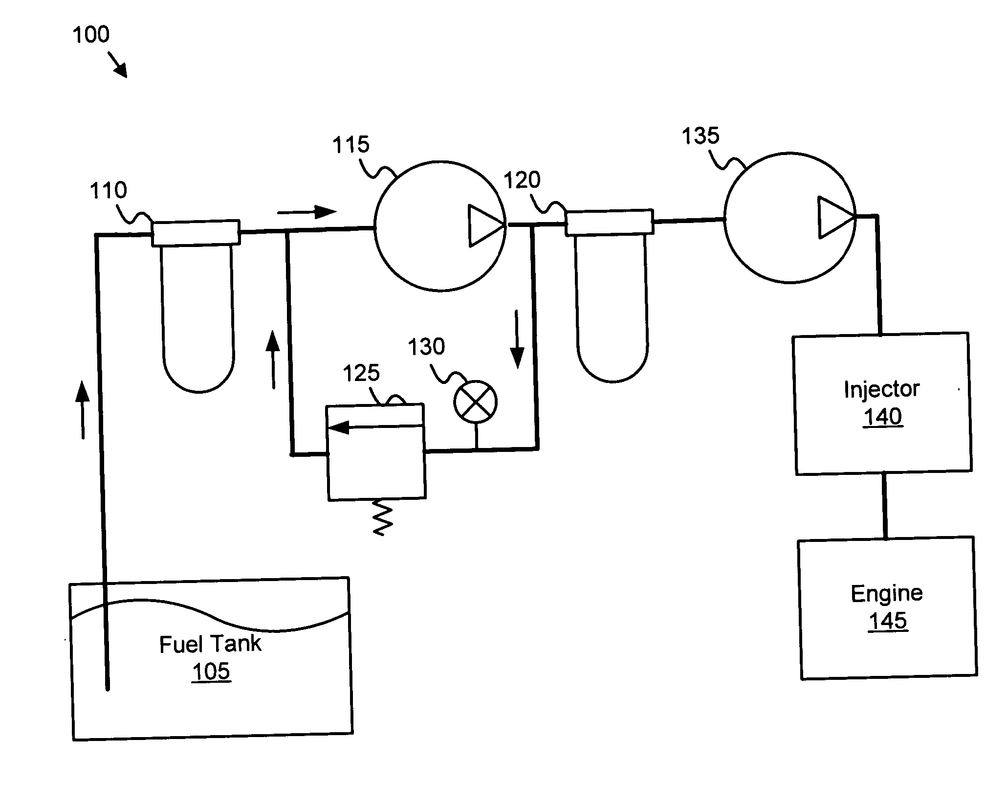
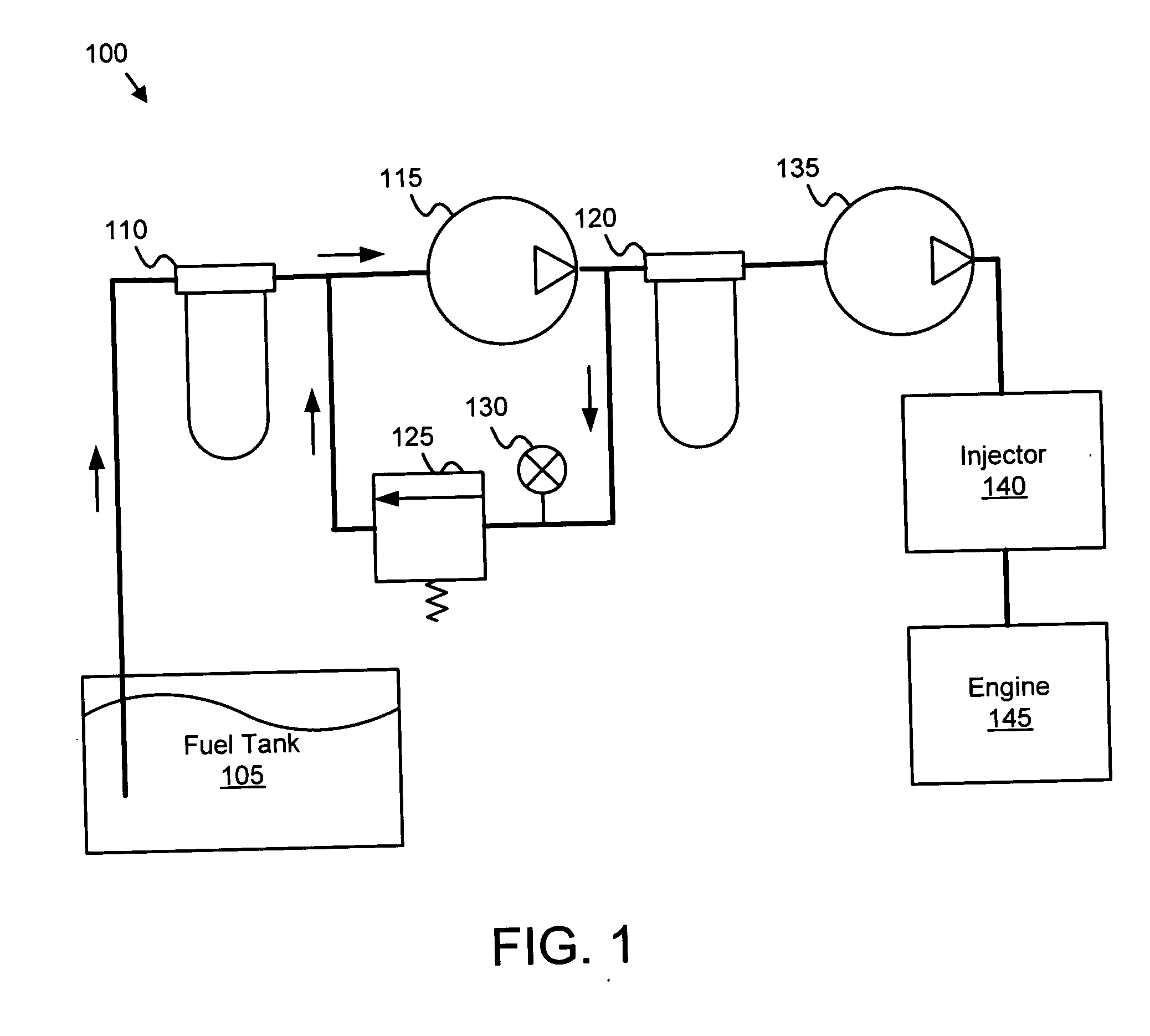
[0043]FIG. 1 is a schematic ...


PUM

PropertyMeasurementUnit
hydrophilicaaaaaaaaaa
wettingaaaaaaaaaa
perimeteraaaaaaaaaa

Abstract

An apparatus, system, and method are disclosed for multistage water separation. A first separation layer separates water droplets from a fuel flow by repelling the first water droplets. A coalescing layer may coalesce fine water droplets in the fuel flow. In one embodiment, a centrifugal separator directs the fuel flow tangentially to a filter wall and the centrifugal force of the fuel flow directed tangentially along the filter wall biases water droplets from the fuel flow. A second separation layer separates second water droplets from the fuel flow.

Description

BACKGROUND OF THE INVENTION [0001] 1. Field of the Invention [0002] This invention relates to separating water and more particularly relates to multistage water separation and fuel filtration. [0003] 2. Description of the Related Art [0004] Hydrocarbon-based liquid fuels such as diesel fuel frequently include quantities of water. The water may be emulsified in the fuel and present in the form of water droplets. Internal combustion engines such as diesel engines typically separate the water from the fuel before combusting the fuel. A fuel water separator (“FWS”) or a fuel water coalescer may be used to separate the free and emulsified water from the fuel. Separating the water from the fuel improves and enhances the performance of the engine by reducing corrosion and erosion. [0005] There are two general categories of devices used to separate water from fuel: single stage stripping FWS and two-stage fuel water coalescing-stripping FWS. Both single stage and two stage FWS are effective...

Claims


Application Information

Patent Timeline
Patent Type & Authority Applications(United States)
IPC IPC(8): C02F9/00
CPCB01D36/003Y10S210/05
Inventor JIANG, ZEMINLOFTIS, TED S.JOHNSON, MARK J.VERDEGAN, BARRY M.
Owner CUMMINS FILTRATION IP INC
Why Eureka
Try Eureka