Tapered roller bearing and transmission bearing apparatus

a technology of transmission bearings and tapered roller bearings, which is applied in the direction of roller bearings, mechanical equipment, bearings, etc., can solve the problems of affecting the total the mechanical internal resistance of tapered roller bearings is very small, and the running torque of tapered roller bearings is reduced, so as to reduce the frictional resistance of the rolling surface and reduce the rotation loss of the apparatus , the effect of reducing the contact area between the rolling conta

Inactive Publication Date: 2007-02-22
JTEKT CORP
View PDF5 Cites 22 Cited by
  • Summary
  • Abstract
  • Description
  • Claims
  • Application Information

AI Technical Summary

Benefits of technology

[0017] According to the transmission bearing apparatus, as has been described above, since the contact areas between the individual rolling contact surfaces and the raceway surfaces can be reduced properly and the sliding resistance between the large end face of the tapered roller ad the rib surface of the inner ring can be reduced, the rotation loss of the apparatus can be reduced.
[0018] According to the tapered roller bearing and the transmission bearing apparatus of the invention, the contact areas between the rolling cont

Problems solved by technology

However, there had been no attempt to grasp the crown as quantity so as to specify the crowning amount so imparted to thereby reduce the running torque of the tapered roller bearing.
In this case, rolling viscous resistance and agitation loss take a major portion of the running torque of the tapered roller bearing, and mechanical internal resistance of the tapered roller bearing is very small.
Therefore, the mechanical internal resistance

Method used


Image

  • Tapered roller bearing and transmission bearing apparatus
  • Tapered roller bearing and transmission bearing apparatus
  • Tapered roller bearing and transmission bearing apparatus

Examples


example

[0104] Next, the results of a comparison investigation will be described which was made using an example according to the invention and a comparison example in which specific numerical values were set, respectively. Main specification data of the example of the invention and the comparison example are shown in Table 1.

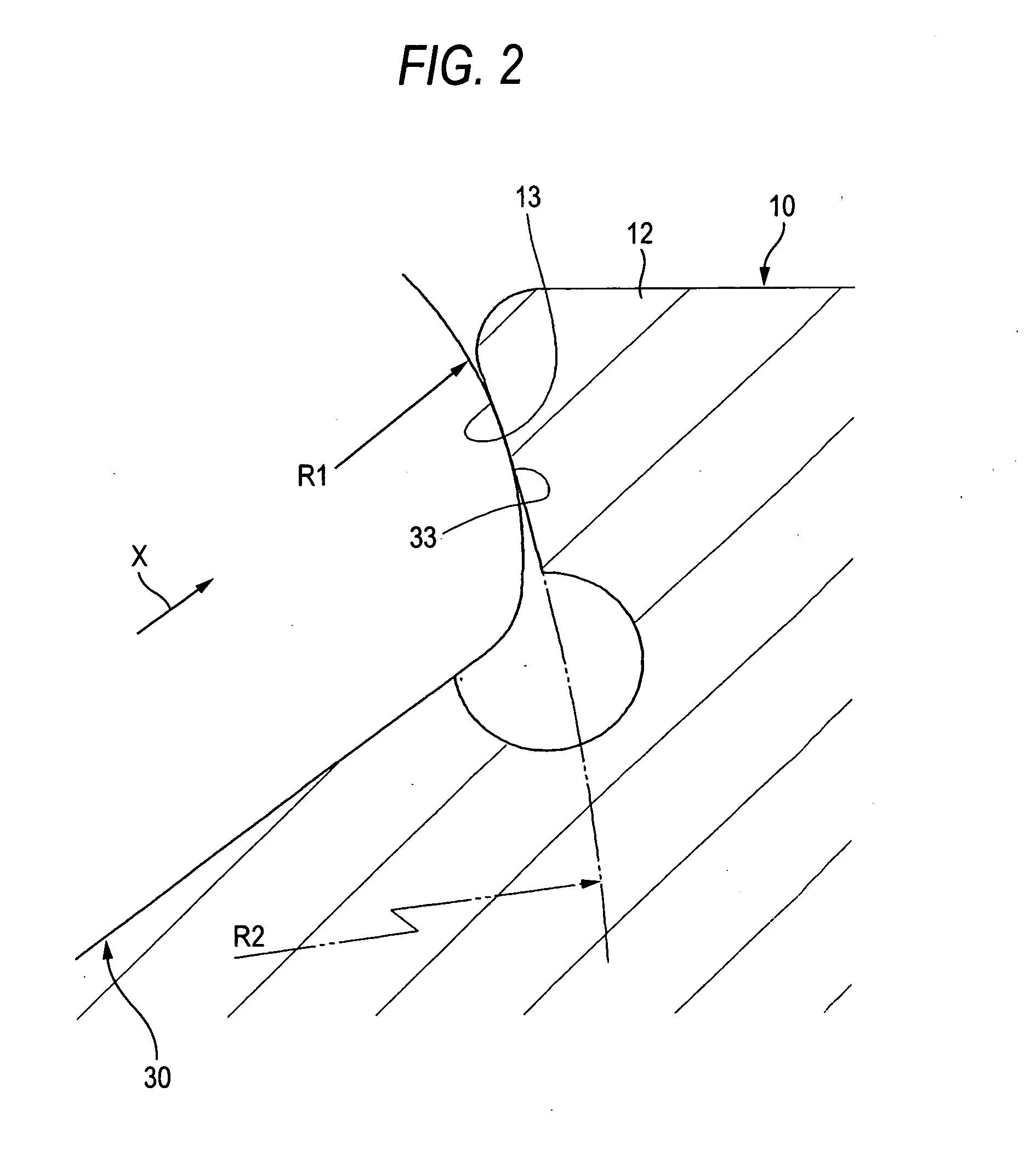
TABLE 1Exam-Com-ple ofparisonIn-Ex-Bearing SpecificationsventionampleMainBore Diameter (mm)3030DimensionsOutside Diameter (mm)7272Width (mm)20.7520.75CrowningOuter Ring Crowning Amount (μm)407Inner Ring Crowning Amount (μm)2812Roller Crowning Amount (μm)44Total Crowning Amount (μm)7627Outer Ring Crowning Rate (%)5326Roller Crowning Rate (%)1130Inner Ring Crowning Rate (%)3744Surface Roughness of Roller Large End Face (σ1, μm)0.030.08Surface Roughness of Inner Ring Large Rib Surface0.040.06(σ2, μm)Ratio between Curvature radius0.380of Roller Large End Face and Curvature radiusof Inner Ring Large rib surface (R1 / R2)

[0105] As to the crowning, the example of the inventio...


PUM


Abstract

A tapered roller bearing includes an outer ring, an inner ring including a large rib surface formed into a concavely curved surfaced recessed in an axial direction, and a plurality of tapered rollers. R1/R2 is in the range of 0.07 to 0.8 where R1 represents radius of curvature of a large end face of the tapered roller and R2 represents a radius of curvature of the concavely curved surface. An arithmetical mean roughness the large end face is in the range of 0.01 to 0.03 μm. A total crowning amount is 50 μm or larger, an outer ring crowning rate, which is a rate of the outer ring crowning amount on the total crowning amount, is 40% or larger, and a roller crowning rate, which is a rate of two times of the roller crowning amount on the total crowning amount is 20% or smaller.

Description

BACKGROUND OF THE INVENTION [0001] The present invention relates to a tapered roller bearing which is preferably used in an automotive pinion shaft supporting apparatus as in a differential and a transaxle and in a transmission of a vehicle or the like, and a transmission bearing apparatus which uses the tapered roller bearing. [0002] In recent years, there has been increasing a demand for improvement in fuel economy of motor vehicles, and in association with the demand, there is expressed a desire to reduce the running torque of tapered roller bearings which are used to support rotational shafts of transmissions and differentials installed on those motor vehicles. [0003] In these situations, as a method of reducing the running torque of a tapered roller bearing, there is a method of reducing the rolling friction of a tapered roller bearing by crowning rolling contact surfaces of tapered rollers and raceway surfaces of inner and outer rings. [0004] As the method like this, as is des...

Claims


Application Information

Patent Timeline
IPC IPC(8): F16C33/58F16C19/36F16C33/36F16C33/66F16H57/021F16H57/037F16H57/038F16H57/039
CPCF16C19/225F16C19/364F16C33/585F16C33/64F16C2240/70F16C23/088F16C2361/61F16C2240/40F16C33/366F16C2240/50
Inventor MATSUYAMA, HIROKICHIBA, HIROYUKITODA, KAZUTOSHI
Owner JTEKT CORP
Why Eureka
Try Eureka