Compaction roller for a fiber placement machine

a technology of fiber placement machine and compaction roller, which is applied in the direction of paper hanging, soldering apparatus,auxillary welding devices, etc., can solve the problems of difficult to apply even pressure to parts lacking radial symmetry, insufficient movement of segments on the single compaction surface, and inability to help parts with radial symmetry

Active Publication Date: 2007-03-01
INGERSOLL MACHINE TOOLS
View PDF10 Cites 67 Cited by
  • Summary
  • Abstract
  • Description
  • Claims
  • Application Information

AI Technical Summary

Benefits of technology

[0010] A first embodiment of the invention is a tool for compacting an article made from composites. The tool includes a mounting bracket, a shaft supported on the mounting bracket, a plurality of segments arranged concentrically along a length of the shaft and driven by the shaft, each segment further comprising a bearing having an outer race and a flexible outer covering, and a first and a second bladder extending through apertures in the plurality of segments on either side of the shaft, wherein each of the plurality of segments is separately movable perpendicularly with respect to the shaft in response to a shape of the article and a pressure in the first or second bladder, for the roller to apply a relatively uniform pressure across the article.

Problems solved by technology

This technique does not help for parts lacking radial symmetry such as prismatic parts.
While this method is useful for radially-symmetric composite parts, such as oxygen bottles or motor housings, it would be difficult to apply even pressure to parts lacking this symmetry.
While this is an improvement, the single compaction surface does not allow the segments to move sufficiently freely to insure compaction in areas where there is a significant change in the diameter or dimension of the part being fabricated.
Thus, tools made according to this patent will not have freedom of movement at least in the central portion of the tool, and the corresponding portion of the part being compacted may not receive sufficient pressure to compact the material.
The fixed segment limits the ability of the tool to conform to the part surface and compact the composite material.

Method used


Image

  • Compaction roller for a fiber placement machine
  • Compaction roller for a fiber placement machine
  • Compaction roller for a fiber placement machine

Examples


Embodiment Construction

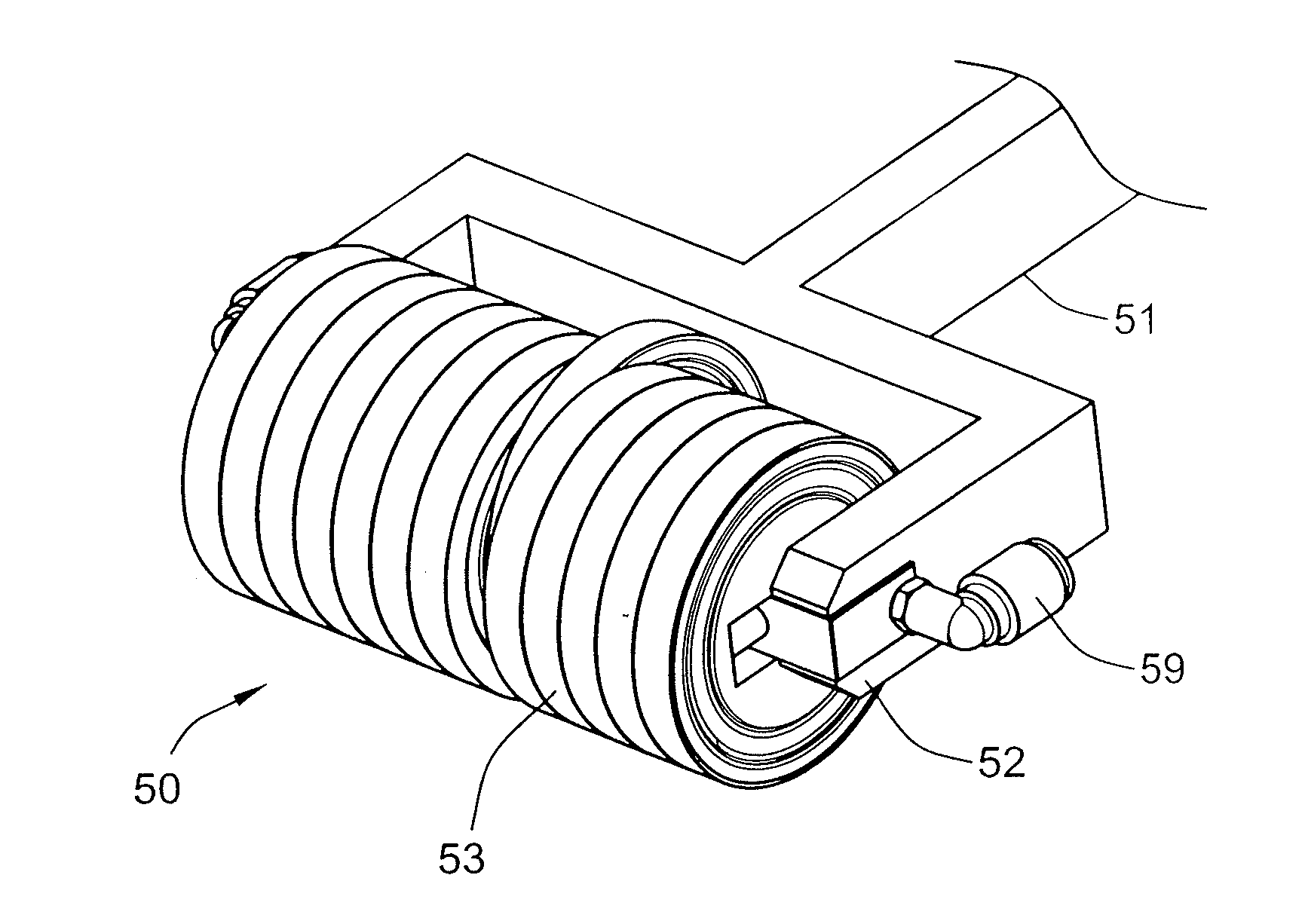
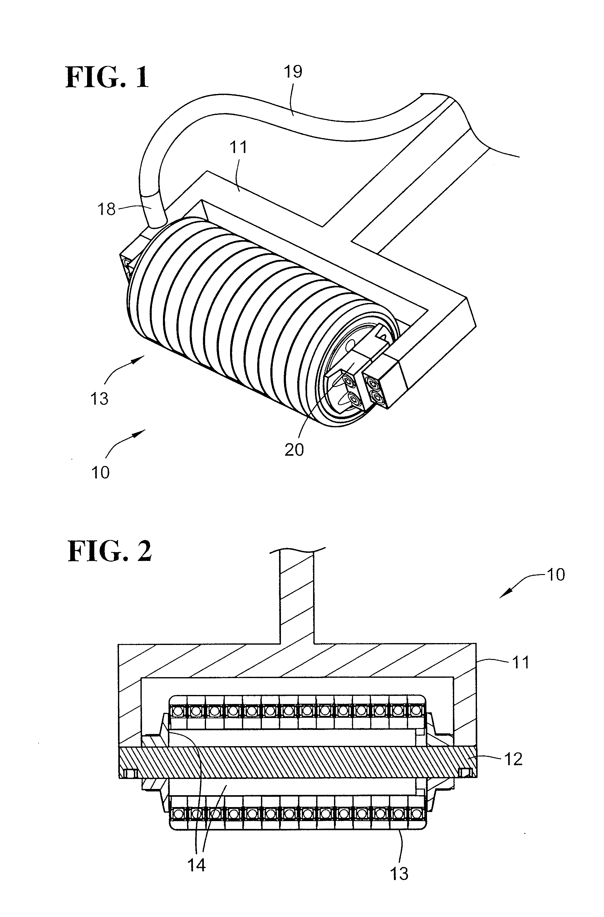
[0038] As mentioned above, it is very important to thoroughly compact a part made from composite materials and in particular from one or more laminae of composite material. These materials are typically, but not necessarily, made from continuous carbon fibers, or other fibers, in a matrix of an epoxy or other thermoset or thermoplastic resin. The tools in which or onto which the materials are deposited may be heated even while filament winding, lay-up or other deposition is taking place. Heating at a moderate temperature warms the materials and makes the resin more pliable and possibly more tacky, allowing for better consolidation of the material and more conformance to the tool. This helps to make a stronger part by insuring better contact between layers of material, to minimize voids in a fabricated part, and to minimize the size of any avoids that may remain afterwards.

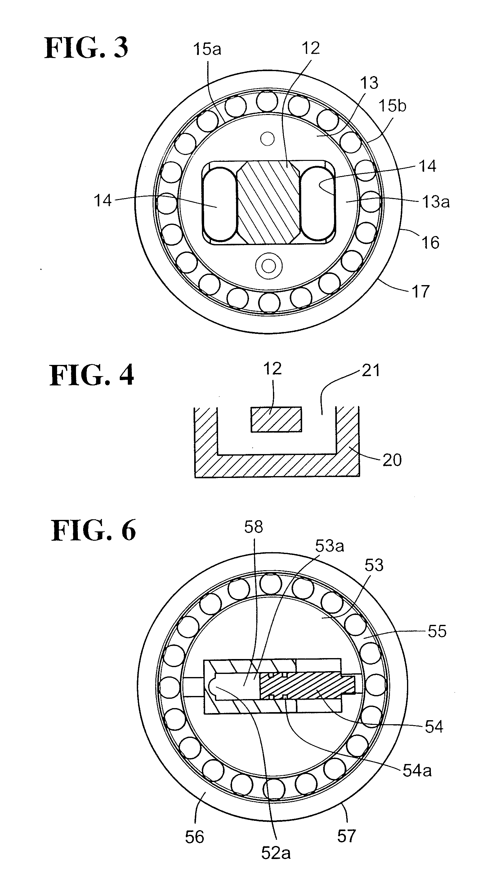
[0039] Embodiments of the invention are principally in the form of a compaction roller made up of a series of t...


PUM

PropertyMeasurementUnit
outer diameteraaaaaaaaaa

Abstract

Tools for compacting composite parts are disclosed. These tools are used while layers of composite material, such as tows or laminae, are being deposited onto a fabricating surface, such as a mold or other forming tool. The compacting tool is typically divided into a series of narrow segments, each segment able to advance or retreat individually so as to conform to the surface of a composite part being formed. Pressurized fluid, such as air or hydraulic fluid, or non-pressurized internal bladders with incompressible fluid, are used to evenly apply pressure to the segments in order to compact the material with which the tool and the segments are in contact. The compacting tool thus helps eliminate voids and helps the material conform to the desired shape on the forming tool.

Description

[0001] This patent application claims the benefit of the filing date under 35 U.S.C. § 119(e) of U.S. Provisional Patent Application No. 60 / 711,403, filed Aug. 25, 2005, which is hereby incorporated by reference in its entirety.FIELD OF THE INVENTION [0002] This invention relates to the forming of composite structures with automated fiber placement machines, and more particularly to compaction rollers of fiber placement heads in automated fiber placement machines. BACKGROUND OF THE INVENTION [0003] Automated fiber placement machines are widely used to manufacture parts, components and structures from composite material. The materials used in automated fiber placement are typically composed of longitudinal fibers and resin consolidated into tapes, or thin strips, commonly known as “tows.” Individual tapes or tows are manipulated by the fiber placement machine to form a band of material that is deposited onto a tool. Parts are built up layer-by-layer, with tapes or tows of composite m...

Claims


Application Information

Patent Timeline
Patent Type & Authority Applications(United States)
IPC IPC(8): B44C7/00
CPCB29C70/382Y10T156/1795Y10T29/49544B29C70/388Y10T156/1788
Inventor MISCHLER, PETER L.TINGLEY, MARK CURTISHOFFMANN, KLAUS
Owner INGERSOLL MACHINE TOOLS
Why Eureka
Try Eureka