Disc Brake Apparatus

a disc brake and disc rotor technology, applied in the direction of axially engaging brakes, brake types, actuators, etc., can solve the problem that the disc brake apparatus cannot brake the disc rotor, and achieve the effect of preventing an excessive increase in the servo load

Inactive Publication Date: 2007-03-01
ADVICS CO LTD
View PDF5 Cites 27 Cited by
  • Summary
  • Abstract
  • Description
  • Claims
  • Application Information

AI Technical Summary

Benefits of technology

[0008] An object of the present invention is to solve the above-mentioned problems in the conventional disc brake apparatus and to provide a disc brake apparatus which can brake a disc rotor in a predetermined braking mode even when coefficient of friction between a pad and the disc rotor varies.
[0011] According to the disc brake apparatus of the present invention, at the time of braking, an output of the actuator, which operates in accordance with an operation force, and a servo load which the servomechanism produces can be applied to the braking piston, which pushes the pad toward the disc rotor for braking the disc rotor. Thus, even though the output of the actuator is small, a large braking force can be produced, thereby allowing a reduction in the size (a reduction in output) of the actuator.
[0012] The changing means increases or decreases a servo load to be applied to the braking piston, in accordance with the operation force and the anchor load. For example, when the coefficient of friction between the pad and the disc rotor decreases (increases) as compared with a predetermined value because of entry of water or thermal fading, and thus the friction force between the pad and the disc rotor decreases (increases) as compared with a predetermined value, with a resultant decrease (increase) in the anchor load as compared with a predetermined value which is determined by the current operation force, the changing means can increase (decrease) the servo load as compared with the predetermined value.
[0014] In the case where the servo load to be applied to the braking piston increases as compared with the predetermined value, an increase in the servo load is up until the braking force which the disc brake apparatus produces assumes approximately the predetermined value, thereby preventing an excessive increase in the servo load to be applied to the braking piston.

Problems solved by technology

However, since the oil pressure (servo oil pressure) which is applied to the braking piston through the pressure-increasing control valve is merely an oil pressure converted from the anchor load, the following problem arises.
As a result, the disc brake apparatus fails to brake the disc rotor in a predetermined braking mode (a braking mode for the case where the coefficient of friction is the predetermined value).

Method used


Image

  • Disc Brake Apparatus
  • Disc Brake Apparatus
  • Disc Brake Apparatus

Examples


first embodiment

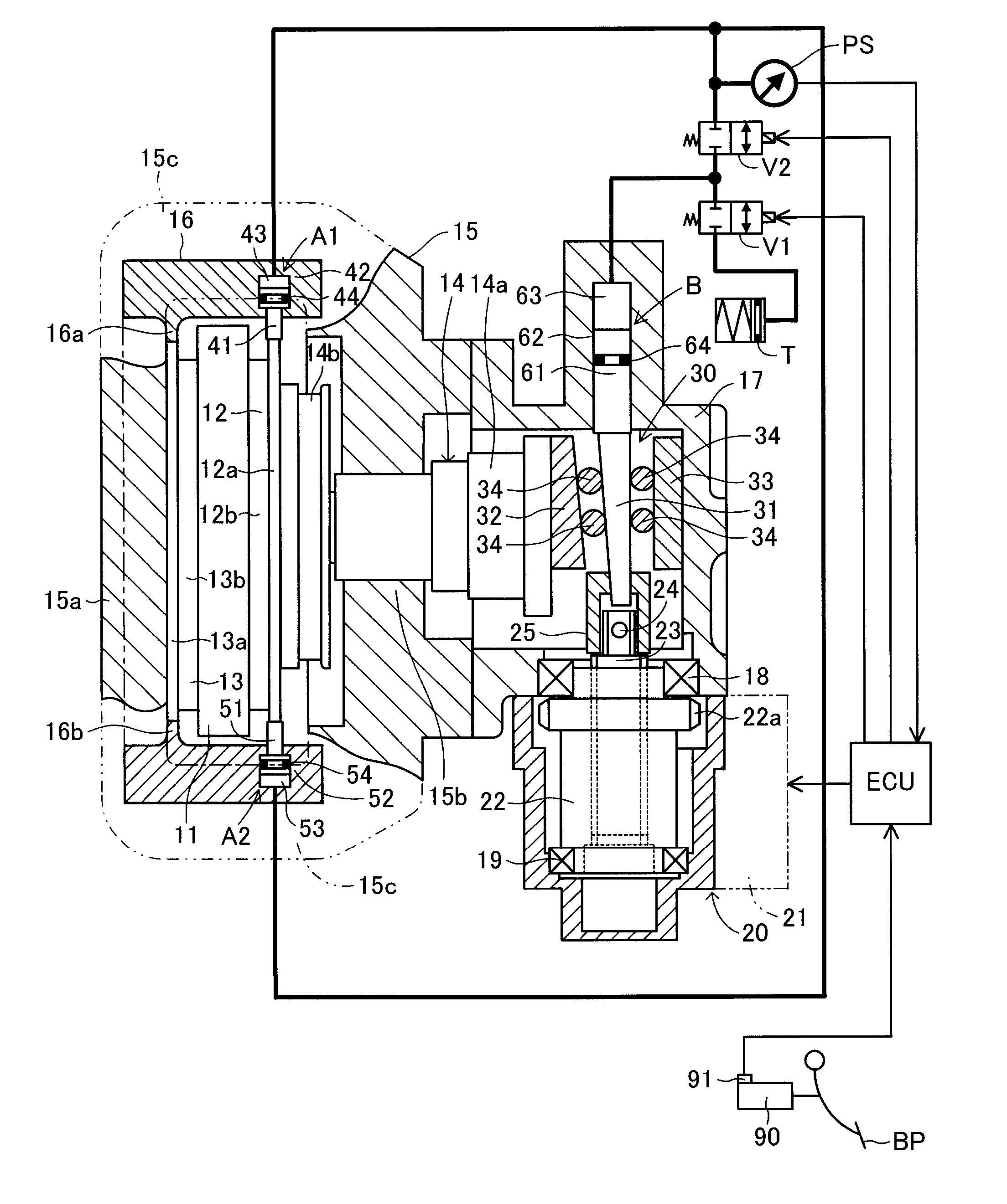
[0041] In the thus-configured disc brake apparatus of the first embodiment, when the brake pedal BP is stepped on, the electric motor 21 is rotationally driven in the regular direction (braking direction). A rotational drive force of the electric motor 21 is converted to an axial drive force (a drive force directed downward in FIG. 1) of the screw shaft 23 via the nut 22. The wedge transmission mechanism 30 converts the axial drive force of the screw shaft 23 to an axial drive force (a drive force directed leftward in FIG. 1) of the braking piston 14 and transmits the axial drive force to the braking piston 14.

[0042] By the above process, the braking piston 14 is axially driven and pushes the inner pad 12 toward the disc rotor 11 and presses it against the disc rotor 11, and an associated reaction force causes the reaction-force arm portion 15a of the caliper 15 to push the outer pad 13 toward the disc rotor 11 and press it against the disc rotor 11, whereby the inner pad 12 and the...

second embodiment

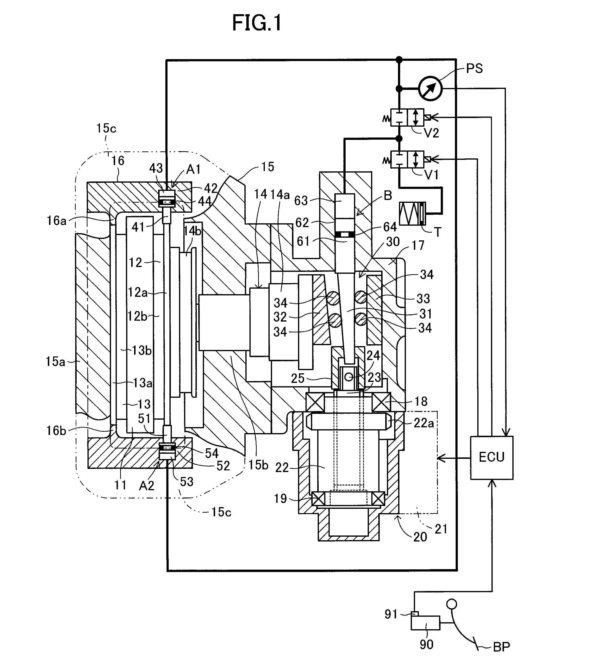
[0060] The second embodiment employs the changeover valve V5 which functions as follows: in the case where a positive pressure is built up in the oil chamber 75, while a negative pressure is built up in the oil chamber 76, the changeover valve V5 establishes communication between the oil chamber 75 and the pressure-increasing solenoid valve V2 and shuts off communication between the oil chamber 76 and the pressure-increasing solenoid valve V2; and in the case where a negative pressure is built up in the oil chamber 75, while a positive pressure is built up in the oil chamber 76, the changeover valve V5 shuts off communication between the oil chamber 75 and the pressure-increasing solenoid valve V2 and establishes communication between the oil chamber 76 and the pressure-increasing solenoid valve V2. However, as shown in FIG. 4, in place of the changeover valve V5, a pair of check valves V5a and V5b may be employed.

third embodiment

[0061] The above-described embodiments employ the motor-driven actuator 20 as an actuator which operates in accordance with the operation force. However, as shown in FIG. 5, which shows the present invention, the present invention can be embodied by employing a hydraulic actuator 120 as an actuator which operates in accordance with the operation force, and a stepped braking piston 114 which is pushed by means of the hydraulic actuator 120 and a servo cylinder 162, which serves as a servomechanism.

[0062] The hydraulic actuator 120 of the third embodiment shown in FIG. 5 is a brake master cylinder which operates in response to the driver stepping on the brake pedal BP. An oil pressure which is built up in the hydraulic actuator 120 (an oil pressure which depends on the operation force) can be detected by a sensor 121 and can be supplied to an oil chamber R1 where a small-diameter portion 114a of the braking piston 114 is exposed. The servo cylinder 162 is provided integrally with the ...


PUM


Abstract

In a disc brake apparatus, by means of an actuator which operates in accordance with an operation force, a braking piston fitted into a cylinder portion of a caliper is axially driven so as to push a pad toward a disc rotor. A friction force in a circumferential direction of the disc rotor between the pad and the disc rotor is taken out as an anchor load, and is converted to a servo load by means of a servomechanism. The servo load is applied to the braking piston. The servomechanism is equipped with a hydraulic mechanism (a pressure-reducing control valve, a pressure-increasing control valve, and a reservoir tank) capable of increasing or decreasing the servo load. An electric controller controls the hydraulic mechanism in accordance with the operation force and the anchor load.

Description

CROSS REFERENCE TO RELATED APPLICATION [0001] This application is based on and claims under 35 U.S.C. sect. 119 with respect to Japanese Patent Application No. 2005-253589 filed on Sep. 1, 2005, the entire content of which is incorporated herein by reference. BACKGROUND OF THE INVENTION [0002] 1. Field of the Invention [0003] The present invention relates to a disc brake apparatus, and more particularly to a disc brake apparatus configured such that, by means of an actuator which operates in accordance with an operation force (e.g., brake-pedal stepping-on force), a braking piston which is fitted into a cylinder portion of a caliper in an axially slidable manner is axially driven so as to push a pad toward a disc rotor; a friction force in a circumferential direction of the disc rotor between the pad and the disc rotor is taken out as an anchor load (braking reaction-force); and a servomechanism converts the anchor load to a servo load, which is applied to the braking piston. [0004]...

Claims


Application Information

Patent Timeline
Patent Type & Authority Applications(United States)
IPC IPC(8): F16D55/46F16D65/18
CPCF16D65/18F16D2121/02F16D2121/14F16D2127/085F16D2127/10
Inventor MURAYAMA, TAKASHI
Owner ADVICS CO LTD
Why Eureka
Try Eureka