Method and apparatus for improving noise discrimination using enhanced phase difference value

a phase difference value and noise discrimination technology, applied in the field of noise discrimination, can solve the problems of increased computational costs, accuracy compromises in analysis windows, and improved efficiency, and achieve the effect of improving noise discrimination

Inactive Publication Date: 2007-03-01
DOLBY LAB LICENSING CORP
View PDF64 Cites 57 Cited by
  • Summary
  • Abstract
  • Description
  • Claims
  • Application Information

AI Technical Summary

Benefits of technology

[0015] In accordance with one aspect of the invention, there is provided a method for improving noise discrimination in a system having a plurality of sensors each generating a sensor input signal representable by an input vector having phase and magnitude components in response to a signal stimulus, the plurality of sensors being arranged to have an on-axis direction. This method includes generating from at least two input vectors an input phase difference value, enhancing the input phase difference value as a function of the location of the signal stimulus relative to the on-axis direction, generating two output vectors corresponding to the two input vectors, the two output vectors having a phase difference based on the enhanced input phase difference value, and combining the two output vectors.
[0016] In accordance with a further aspect of the invention, there is provided a method for improving noise discrimination in a system having a plurality of sensors each generating a sensor input signal representable by an input vector having phase and magnitude components in response to a signal stimulus, the plurality of sensors being arranged to have an on-axis direction. This method includes generating an attenuation factor as a function of a phase difference from two input vectors, combining the two input vectors to obtain an output vector, and attenuating the output vector by the attenuation factor.
[0017] In accordance with a further aspect of the invention, there is provided a method for improving noise discrimination in a system having a plurality of sensors each generating an input signal representable by an input vector having a phase component and a magnitude component, the plurality of sensors arranged to have an on-axis direction. The method includes using a first pair of sensors to obtain a coarse vector phase difference corresponding to a coarse measurement of an angle of arrival of a signal input source relative to the on-axis direction, using a second pair of sensors to obtain a fine vector phase difference corresponding to a fine measurement of the angle of arrival of the signal input source, generating an input phase difference value from the coarse and fine vector phase differences, enhancing the input phase difference value as a function of the angle of arrival to generate an output phase difference value, generating first and second output vectors having a phase difference based on the output phase difference value, and combining the first and second output vectors.

Problems solved by technology

Although there are choices for the analysis window, such as the Harming window, that will reconstruct the time domain signal accurately without the added complexity and computational cost of a synthesis window, such analysis windows suffer from accuracy compromises to achieve the improved efficiency.
However, there are costs to this approach, including the additional sensor elements and associated amplifiers and A / D converters (in a digital system) or filters (in an analog system), the added computational costs for processing all the sensor signals, the result that the beam pattern becomes complex with many added side lobes in which the sensitivity of the system to unwanted signal sources is relatively high (that is, the system has relatively low noise immunity), the large physical size of the sensor array, and non-uniform frequency response for off-axis signals, among others.
For these reasons, another method called “super resolution” beamforming has been employed, wherein the increased aperture is filled with additional sensor elements, but the elements are non-uniformly spaced and the resulting sensor signals are non-uniformly weighted in amplitude.
However, to be successful the super resolution approach still requires a great number of sensor elements and associated circuitry and suffers from significantly increased computational costs, high side lobe sensitivity, large physical size, and non-uniform off-axis frequency response.
In general, although the side lobes can be reduced with such an approach, the tradeoffs include a wider main lobe, high complexity and cost, and the retention of a high number of sensors.
Thus, to be effective in most real-life situations where there are numerous noise sources and multiple-reflections of those noise sources, the number of sensors must be large, along with the associated high system complexity, large compute power requirement, and high cost.
Further, such systems, because the nulls are very narrow, require adaptive circuit techniques to accurately center the nulls on the noise source directions, and these adaptive methods are slow to adapt, allowing significant noise to pass during the adaptation time.
One common characteristic of these prior art systems is that the null or nulls created by these methods are quite narrow.

Method used


Image

  • Method and apparatus for improving noise discrimination using enhanced phase difference value
  • Method and apparatus for improving noise discrimination using enhanced phase difference value
  • Method and apparatus for improving noise discrimination using enhanced phase difference value

Examples


Embodiment Construction

[0061] In accordance with an aspect of the invention, a novel approach based on enhancing the performance of beamforming systems is disclosed. As a general aim, an aspect of the invention operates on the principle of enhancing or enlarging the nulls of a beam pattern created by such a beamforming system.

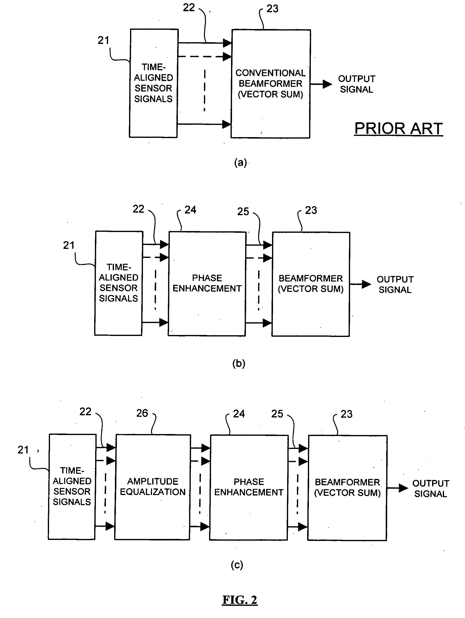
[0062] The novel approach, in accordance with an aspect of the invention, is to widen the nulls—that is, regions 37 and 38 in FIG. 3—rather than to narrow the main lobes 35 and 36 of a beamforming system. This approach improves directionality, but by way of a unique and advantageous apparatus and method. By widening the nulls using the inventive method, the improved directionality is accomplished without increasing the number of sensor elements and associated amplifiers and A / D converters (in a digital system) or filters (in an analog system), with reduced computational costs for processing the sensor signals, with the result that the beam pattern is simple without added side lobes ...


PUM


Abstract

Noise discrimination in signals from a plurality of sensors is conducted by enhancing the phase difference in the signals such that off-axis pick-up is suppressed while on-axis pick-up is enhanced. Alternatively, attenuation / expansion are applied to the signals in a phase difference dependent manner, consistent with suppression of off-axis pick-up and on-axis enhancement. Nulls between sensitivity lobes are widened, effectively narrowing the sensitivity lobes and improving directionality and noise discrimination.

Description

FIELD OF THE INVENTION [0001] The invention relates to noise discrimination in signal detection and processing. DESCRIPTION OF THE RELATED ART [0002]FIG. 1 is a block diagram of a conventional real-time frequency domain signal processing system 10 employing what is sometimes referred to as the frequency sub-band method or the frame-overlap-and-add method. This method uses a circuit 11 to divide incoming sampled temporal signal information into blocks of data referred to as frames. The sampled data can be provided directly from a digital sensor or other processing system, or can be provided from an analog sensor or processing system via a standard Analog-to-Digital conversion (A / D or ADC) method (not shown). The frames can be adjacent or overlapping. Since the data are samples of time domain data, all samples within a frame have no imaginary component, and the data is strictly “real.” If required by the application, these frames of data then may be multiplied in a multiplication circ...

Claims


Application Information

Patent Timeline
Patent Type & Authority Applications(United States)
IPC IPC(8): H04R3/00
CPCH04R3/005H04R3/00H03D3/22H04R1/40H04S5/00
Inventor TAENZER, JON C.SPICER, BRUCE G.
Owner DOLBY LAB LICENSING CORP
Why Eureka
Try Eureka