Using laser shock loads to debond structures

a technology of laser shock load and structure, applied in the field of structures, can solve problems such as accidental damage of aircra

Active Publication Date: 2007-03-08
THE BOEING CO
View PDF6 Cites 25 Cited by
  • Summary
  • Abstract
  • Description
  • Claims
  • Application Information

AI Technical Summary

Problems solved by technology

It is not unusual for aircraft to incur accidental damage in the course of everyday airport operations and maintenance.
Removing composite material over regions of strong bonds can be an arduous and dirty task which involves cutting, grinding and / or machining tough material.

Method used


Image

  • Using laser shock loads to debond structures
  • Using laser shock loads to debond structures
  • Using laser shock loads to debond structures

Examples


Embodiment Construction

[0011] The following description of various embodiments of the present invention is merely exemplary in nature and is in no way intended to limit the invention, its application, or uses. Although one or more implementations are described with reference to composite structures, the invention is not so limited. Implementations also are contemplated in connection with structures including materials other than or in addition to composite materials. For example, the invention could be practiced relative to structures in which composites or metals are bonded to metals such as titanium and / or aluminum. Furthermore, implementations of the invention are contemplated not only in aerospace applications but also in relation to many other applications in which selective debonding may be desirable.

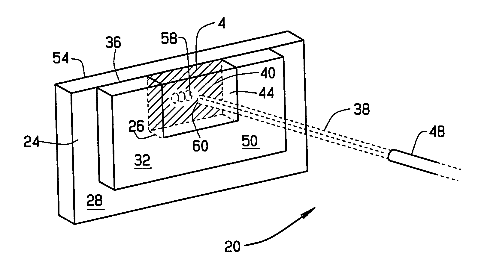
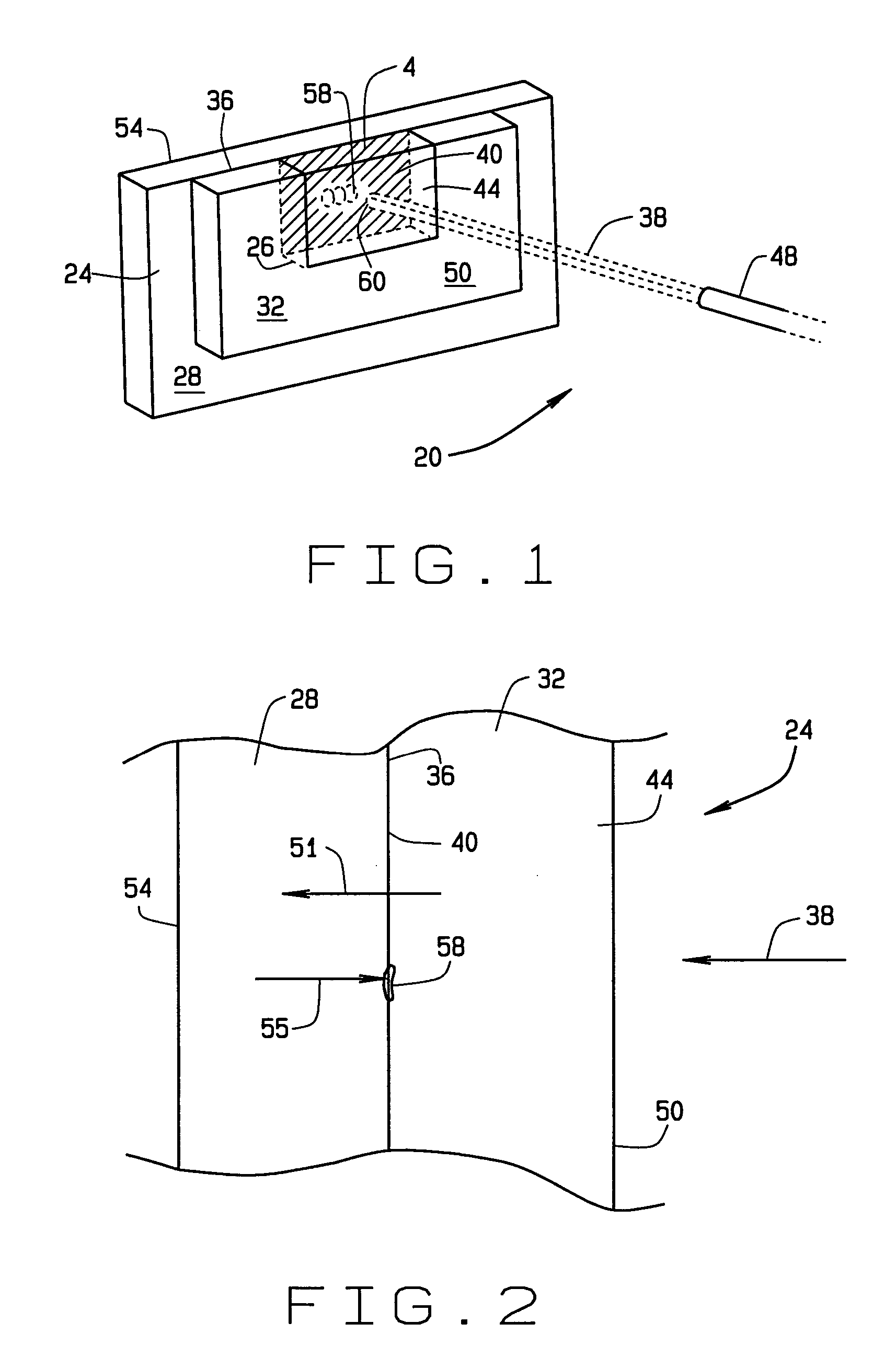
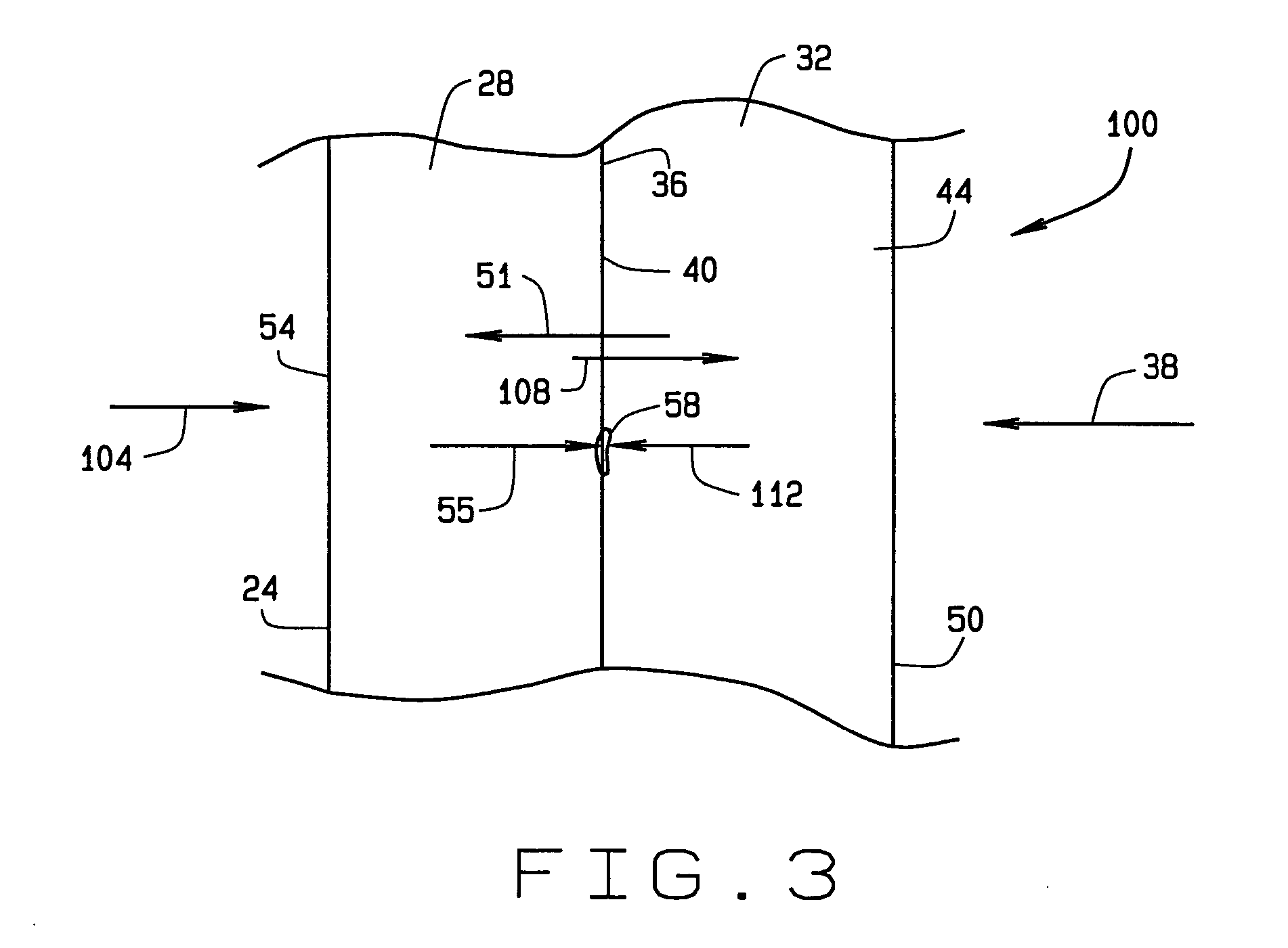
[0012] Various implementations of the invention are directed to using laser-generated stress waves to break bonds within a composite structure. More specifically and for example, a controlled shock wav...


PUM

PropertyMeasurementUnit
distanceaaaaaaaaaa
distanceaaaaaaaaaa
diametersaaaaaaaaaa

Abstract

A method of disassembling at least a portion of a structure that includes parts which are bonded together. The method includes selecting a subsurface depth within the structure at which it is desired to cause debonding of the structure. A laser beam diameter, pulse width and power level predetermined to produce a peak tensile stress within the structure at the selected depth are selected. A laser having the selected beam diameter is used to apply a shock load at the selected pulse width and power level to the structure. Using this method, damaged or unwanted aircraft skin, patches or overlays on structure can be removed more cleanly and simply than milling, grinding or other mechanical methods.

Description

FIELD OF THE INVENTION [0001] The present invention relates to structures having parts which are bonded together and more particularly (but not exclusively) to using a laser to selectively apply a shock load to cause debonding of a subsurface portion of a structure. BACKGROUND OF THE INVENTION [0002] Composite materials are widely used in aircraft applications. It is not unusual for aircraft to incur accidental damage in the course of everyday airport operations and maintenance. Repairing impact damage typically involves the removal of material over bonded substructure joints. Removing composite material over regions of strong bonds can be an arduous and dirty task which involves cutting, grinding and / or machining tough material. SUMMARY OF THE INVENTION [0003] The present invention, in one aspect, is directed to a method of disassembling at least a portion of a structure that includes parts which are bonded together. The method includes selecting a subsurface depth within the struc...

Claims


Application Information

Patent Timeline
Patent Type & Authority Applications(United States)
IPC IPC(8): B29C63/00
CPCB23K26/367Y10T29/49755B29C2791/009B23K26/0036B23K26/0069B23K26/009B23K26/0621B23K26/063B23K26/18C09J5/06C09J2205/302C09J2205/31Y10S156/937Y10T29/49721Y10T156/1158Y10T156/1168Y10T156/1153Y10T29/49821Y10T156/19B29C65/76B23K26/0006B23K26/364B23K26/0619B23K26/0622B29K2995/0027B29C66/1122B29C66/472B29C66/721B29C66/7422B29C66/7428B23K26/356B23K2103/42C09J2301/502C09J2301/416
Inventor BOSSI, RICHARD H.BRUSTAD, VAL G.
Owner THE BOEING CO
Why Eureka
Try Eureka