Method and apparatus of global de-noising for cone beam and fan beam CT imaging

a global image denoising and computed tomography technology, applied in the field of ct imaging, can solve the problems of inefficient and time-consuming methods, introduce some imaging blur, reduce high frequency information, etc., and achieve the effect of reducing the required x-ray dose, more effective and efficien

Active Publication Date: 2007-03-08
UNIVERSITY OF ROCHESTER
View PDF2 Cites 41 Cited by
  • Summary
  • Abstract
  • Description
  • Claims
  • Application Information

AI Technical Summary

Benefits of technology

[0026] Artifacts and efficiency can be evaluated for clinical data. The final noise reduction factors and minimum required exposure level can be determined for the application of interest. Different CBCT denoising protocols can be incorporated with different applications and different data acquisition protocols to reduce the required x-ray dose without compromising the image quality.
[0027] The global denoising technique according to the present invention for cone beam CT imaging (fan beam CT imaging) is to apply the digital reconstruction filter (DRF)-based denoising technique and / or the wavelet transfer (WT)-based denoising technique for projection image data or filtered projection data prior to 3D backprojection process. These approaches are expected to be more effective and efficient.

Problems solved by technology

One is the continuously varying error caused by the electrical noise or roundoff errors, and the other is the discretely varying error due to the X-ray photon fluctuation.
The error is caused by the noise based on the X-ray photon fluctuation.
Those methods are inefficient and time consuming
However, it will also reduce high frequency information and introduce some imaging blur.
If Fw is the reduction factor of cone beam CT image noise with a 2D (1D for fan beam CT) wavelet-transform-based denoising algorithm, if only a WT-based denoising technique is applied, then Fw is not constant and uniform even for the same application.
This becomes a disadvantage because an important real-world application of the denoising technique is for clinical data.
In addition, incorporating a WT-based technique into the reconstruction process will significantly increase computational time.
This will not be practical.

Method used


Image

  • Method and apparatus of global de-noising for cone beam and fan beam CT imaging
  • Method and apparatus of global de-noising for cone beam and fan beam CT imaging
  • Method and apparatus of global de-noising for cone beam and fan beam CT imaging

Examples


Embodiment Construction

[0032] A preferred embodiment of the present invention will be set forth in detail with reference to the drawings, in which like reference numerals will refer to like elements or steps throughout.

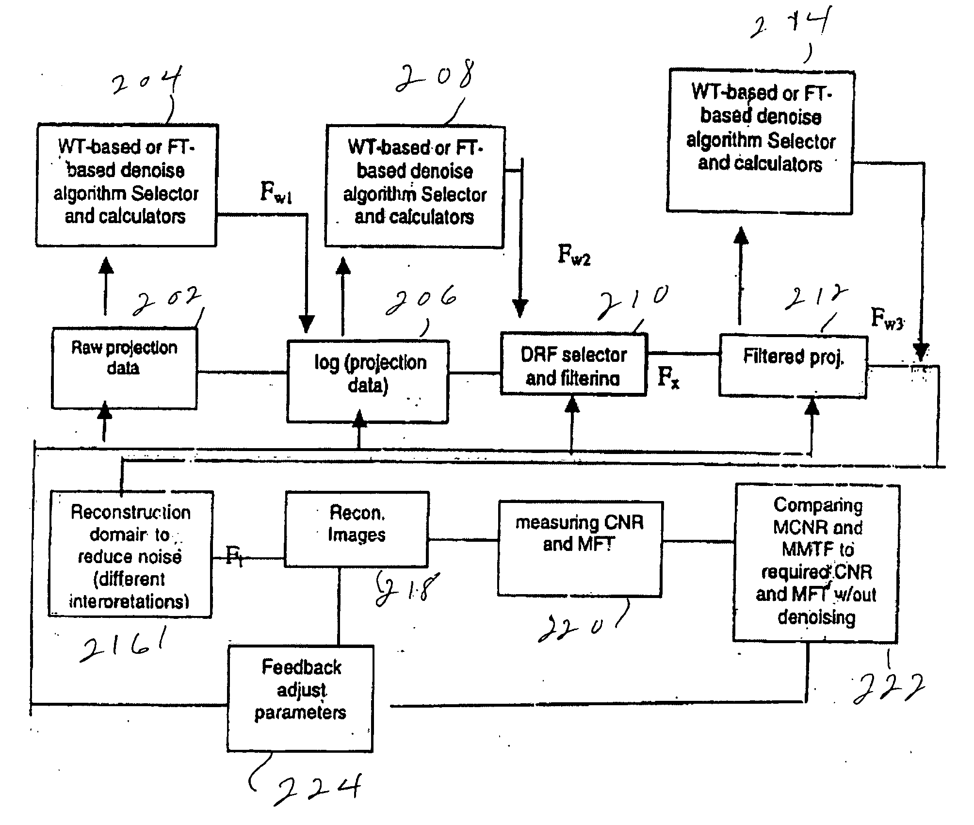
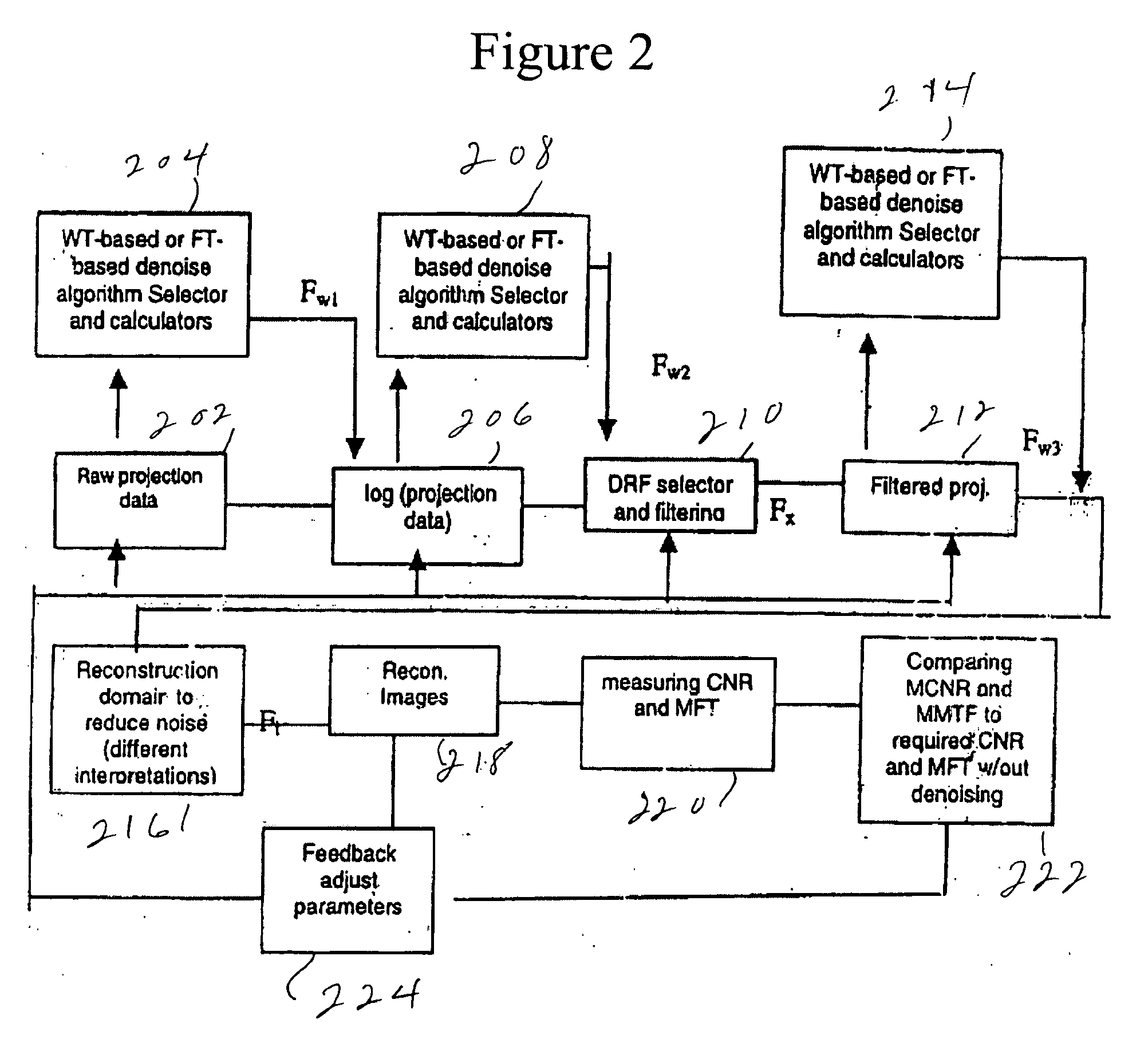
[0033]FIG. 2 shows a flow chart of the preferred embodiment. Steps 202 through 214 are performed in the projection domain, while steps 216 through 224 are performed in the reconstruction domain.

[0034] Raw projection data taken in step 202 are applied to a WT-based or FT-based denoising algorithm selector and calculator in step 204 to produce Fw1. Also, the logarithm of the projection data is computed in step 206. Fw1 is applied to denoise the logarithm of the projection data, and the result is applied in step 208 to a WT-based or FT-based denoise algorithm selector and calculator to produce Fw2. The denoised logarithm of the projection data and Fw2 are applied to a DRF selector and filtering 210, which produces Fx, which is used to produce filtered projections in step 212. The filtered pr...


PUM

PropertyMeasurementUnit
noise ratioaaaaaaaaaa
carrier to noise ratioaaaaaaaaaa
fan beam computed tomographyaaaaaaaaaa

Abstract

Raw cone beam tomography projection image data are taken from an object and are denoised by a wavelet domain denoising technique and at least one other denoising technique such as a digital reconstruction filter. The denoised projection image data are then reconstructed into the final tomography image using a cone beam reconstruction algorithm, such as Feldkamp's algorithm.

Description

REFERENCE TO RELATED APPLICATION [0001] The present application claims the benefit of U.S. Provisional Patent Application No. 60 / 674,335, filed Apr. 25, 2005, whose disclosure is hereby incorporated by reference in its entirety into the present disclosure.STATEMENT OF GOVERNMENT INTEREST [0002] The work leading to the present invention was supported in part by the National Institutes of Health. The government has certain rights in the invention.FIELD OF THE INVENTION [0003] The present invention is directed to an efficient global image denoising algorithm for cone beam and fan beam computed tomography (CT) imaging, so that the proposed algorithm can reduce the noise level while adaptively preserving the image spatial resolution, thereby reducing the radiation exposure dose for CT scanning while obtaining satisfactory image quality for diagnosis. DESCRIPTION OF RELATED ART [0004] It is usually considered that there are two kinds of noise in CT images. One is the continuously varying ...

Claims


Application Information

Patent Timeline
Patent Type & Authority Applications(United States)
IPC IPC(8): H05G1/60A61B6/00G01N23/00G21K1/12
CPCG01N23/046G06T5/10G06T11/005G06T2207/10081G01N2223/419G06T2207/20056G06T2207/20064Y10S378/901G06T5/002
Inventor NING, RUOLA
Owner UNIVERSITY OF ROCHESTER
Why Eureka
Try Eureka