Composite material for drilling applications

a technology of composite materials and drilling applications, applied in the field of composite materials, can solve the problems of low cutting stress, reduced cutting efficiency, and inability to cost-effectively solve the effect of reducing the cost of drilling

Inactive Publication Date: 2007-03-08
SIGALAS IAKOVOS +1
View PDF6 Cites 76 Cited by
  • Summary
  • Abstract
  • Description
  • Claims
  • Application Information

AI Technical Summary

Benefits of technology

[0031] The plurality of granules may be consolidated by applying pressure to the granules, for example, in a confined space such as a die. The consolidated composite is a green state product which has coherency, but which may also be severed, for example, by cutting. A piece which may be severed and removed from the consolidated or coherent composite has flexibility and may be applied to surfaces, which are flat or profiled, e.g. a curved surface. The die for consolidating the granules may be provided with one or both punches profiled such that the green state product has at least o...

Problems solved by technology

However, a cutter with a thick PCD table layer, once a wear scar is formed, attacks the rock by applying the cutting loads on the rock through the part of the PCD table that is in contact with it.
Therefore the cutting stresses are low, and the cutting efficiency is reduced.
Such a technique uses up a significant proportion of the cutter's useful PCD material by fracturing it away, and cannot be cost effective.
The result is that the PCD layer below the top surface wears faster tha...

Method used


Image

  • Composite material for drilling applications
  • Composite material for drilling applications
  • Composite material for drilling applications

Examples


example 1

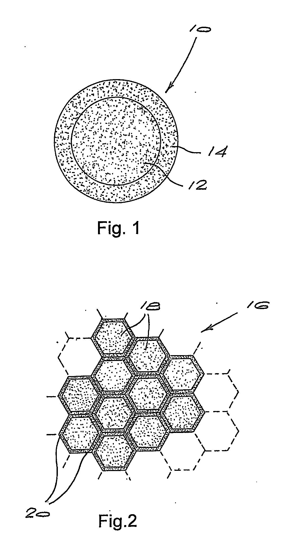
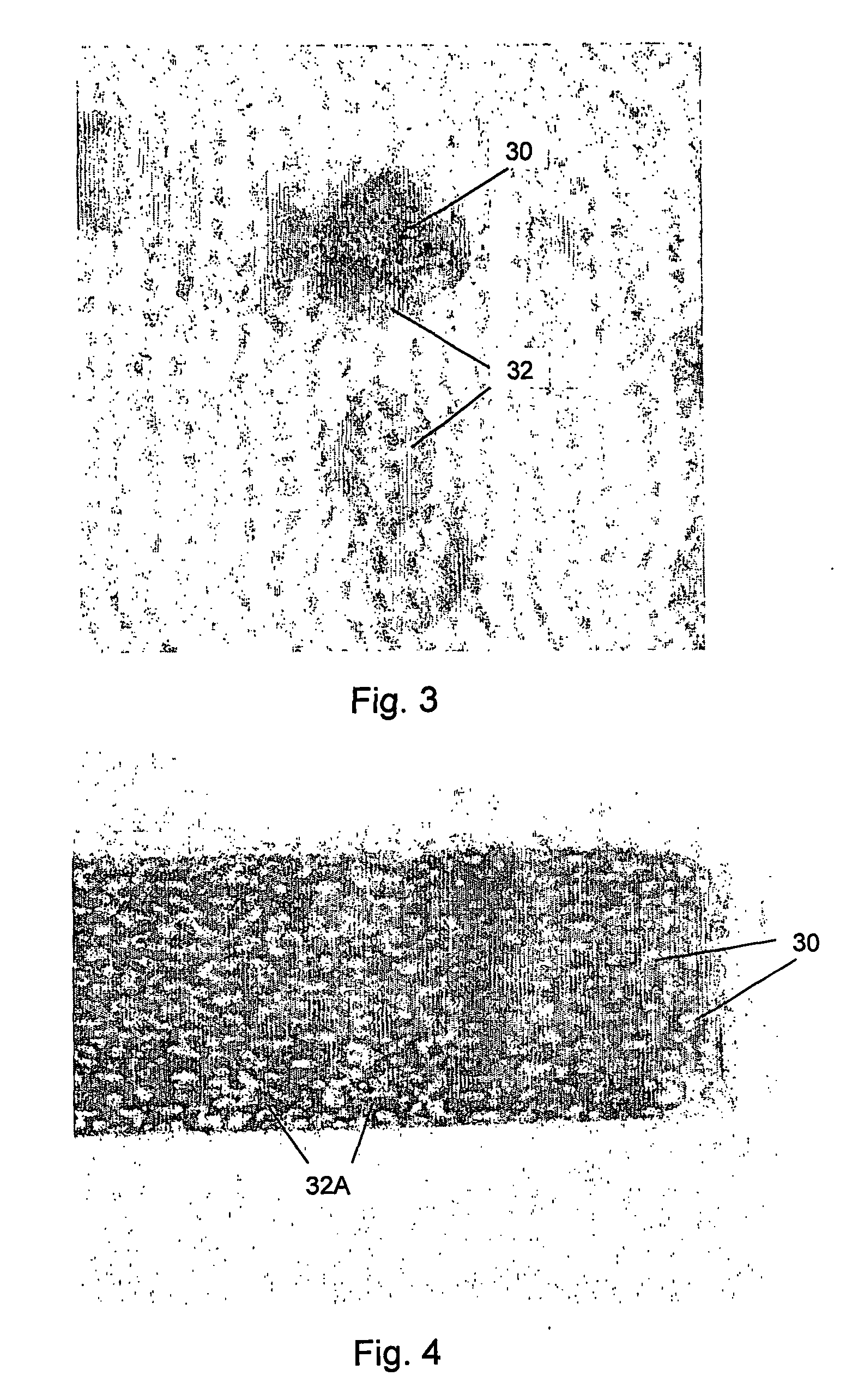
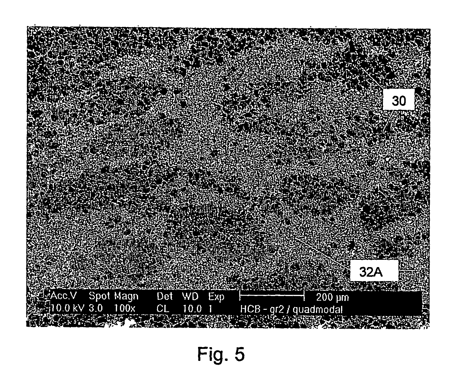
[0052] A solvent based slurry of coarse diamond powder was prepared with approximately 4 wt % organic binder. The slurry was dried and crushed with pestle and mortar to produce green diamond particles screened to about 200 to 300 microns in size. The granules were placed into a pan granulator and rolled while small additions of a fine diamond powder with an organic binder were added to effect coating. Volume % of diamond granules to diamond coating was in the ratio of 1:1. The coated diamond particles are depicted in FIG. 3, where 30 is a coarse diamond granule and 32 the diamond coating. The coated green granules were placed into a reaction cell and covered with a WC-13% Co substrate. The arrangement produced a unit with a PCD layer consisting of sintered diamond granules in a matrix of another sintered diamond type. Binder removal was done in air at 400° C. for 2 hours. The pre-outgassed units were then outgassed in vacuum at 1100° C. for 25 minutes, and loaded into a reaction cap...

example 2

[0053] In example 1, diamond granule shape was uncontrolled leading to irregular shaped granules. As granules can be of any shape, diamond granules of example 2 were made spherical before coating with diamond powder. The spherical shape was achieved by rolling irregular shaped granules in a granulator with additions of diamond powder to coat. The granules were then sieved to achieve 200 to 300 micron sized pellets. These granules were then coated with another diamond powder type. A compact was pressed as in example 1. Whilst not tested, it is expected that such a compact would compare favourably with the compact of example 1.

example 3

[0054] The same procedure as in example 1 was followed except that the granules were admixed and not coated. Granules from coarse grained powder were admixed in a fine grained diamond powder. A compact was pressed as in example 1. In a conventional Paarl granite test, the material tested developed a wear scar of about 0.325 mm, which once again exhibits a very good wear resistance for the PCD material.


PUM

PropertyMeasurementUnit
Grain sizeaaaaaaaaaa
Particle sizeaaaaaaaaaa

Abstract

A composite material consists of a plurality of cores dispersed in a matrix. The cores are formed of ultra-hard material, or the components for making an ultra-hard material. The matrix is formed of the components for making an ultra-hard material of a grade different to that of the cores, and a suitable binder. The ultra-hard material is polycrystalline in nature and is typically PCD or PcBN. The cores are typically provided as granules coated with the components for making an ultra-hard material and the binder. The composite material typically takes on a honeycomb structure of an ultra-hard material and cores within the pores of the honeycomb structure bonded to the honeycomb structure. The pores of the honeycomb structure may be ordered or random.

Description

BACKGROUND OF THE INVENTION [0001] This invention relates to a composite material, a method of making the composite material and a method of making a tool component. [0002] Polycrystalline diamond (herein referred to as PCD) and polycrystalline cubic boron nitride (herein referred to as PcBN) are well known materials used in cutting and abrasive applications. PCD cutters are well-known and widely used in drill bit technology as the cutting element in drill bits used in core drilling, oil and gas drilling, and other similar applications. Such cutters generally comprise a PCD table formed on a hard metal substrate by a high temperature—high pressure sintering process. The substrate is then either brazed on an elongated support, or is directly brazed in a pocket of the drill bit, in a manner that exposes the PCD table to the surface for rock cutting. [0003] It is known that PCD cutters with a thick PCD table can enjoy a prolonged useful life during the drilling operation. This is simpl...

Claims


Application Information

Patent Timeline
IPC IPC(8): D04H13/00B01J3/06C04B35/628C04B35/645E21B10/56E21B10/567
CPCB01J3/065Y10T428/30B01J2203/0655B01J2203/066C04B35/628C04B35/62802C04B35/62836C04B35/62839C04B35/645C04B2235/386C04B2235/427C04B2235/528C04B2235/5427C04B2235/762E21B10/567Y10T428/24942B01J2203/0645Y10T428/249924C04B35/528
Inventor SIGALAS, IAKOVOSMASETE, MOSIMANEGAPE STEPHEN
Owner SIGALAS IAKOVOS
Why Eureka
Try Eureka