Systems and methods of forming particles

a technology of system and particle, applied in the field of system and method of forming particles, can solve the problems of prone to failure, unsuitable for control of very small dispersed phase droplets, and traditional industrial processes typically involve manufacturing equipment built to operate on size scales generally unsuitable for precise control

Inactive Publication Date: 2007-03-08
PRESIDENT & FELLOWS OF HARVARD COLLEGE
View PDF97 Cites 406 Cited by
  • Summary
  • Abstract
  • Description
  • Claims
  • Application Information

AI Technical Summary

Benefits of technology

[0019] In another aspect, the present invention is directed to a method of making one or more of the embodiments described herein, for example, a plurality of particles having an average dimension of less than about 500 micrometers and a distribution of dimensions such that no more than about 5% of the particles have a dimension greater than about 10% of the average dimension. In yet another aspect, the present invention is directed to a method of using one or more of the embodiments described herein. In still another aspect, the present invention is directed to a method of promoting one or more of the embodiments desc

Problems solved by technology

The formation of particles can be carried out in equipment including moving parts (e.g., a blender or device similarly designed to break up material), which can be prone to failure and, in many cases, is not suitable for control of very small dispersed phase droplets.
Spec

Method used


Image

  • Systems and methods of forming particles
  • Systems and methods of forming particles
  • Systems and methods of forming particles

Examples


example 1

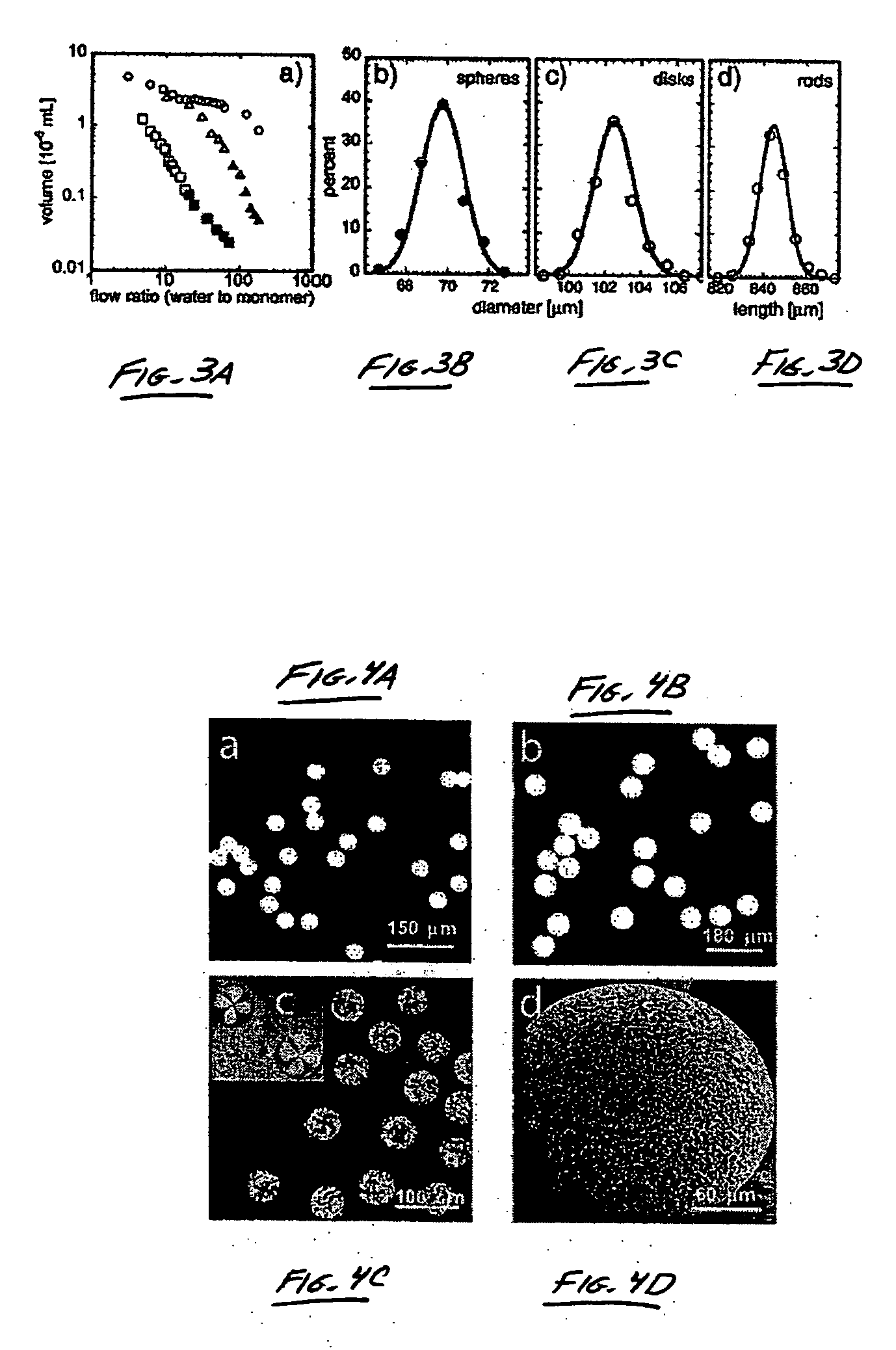
[0077] This example illustrates the formation of substantially monodisperse droplets using flow focusing techniques, where at least 90% of the droplets are within 5% of the median size. Dispersities were determined by curve fitting of the experimental histograms of the size of the particles with Gaussian distributions. The standard deviations were typically on the order of 1%-2% of the mean size.

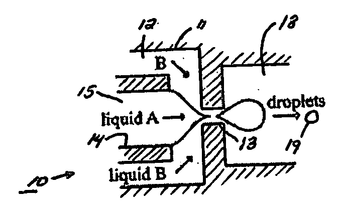
[0078] Various microfluidic flow-focusing devices (“MFFD”) were used in this example to generate fluidic droplets, using techniques similar to those described in International Patent Application No. PCT / US03 / 20542, filed Jun. 30, 2003, entitled “Method and Apparatus for Fluid Dispersion,” by Stone, et al., published as WO 2004 / 002627 on Jan. 8, 2004; and International Patent Application No. PCT / US2004 / 027912, filed Aug. 27, 2004, entitled “Electronic Control of Fluidic Species,” by Link, et al., each incorporated herein by reference. A schematic diagram of a microfluidic flow-focusing devic...

example 2

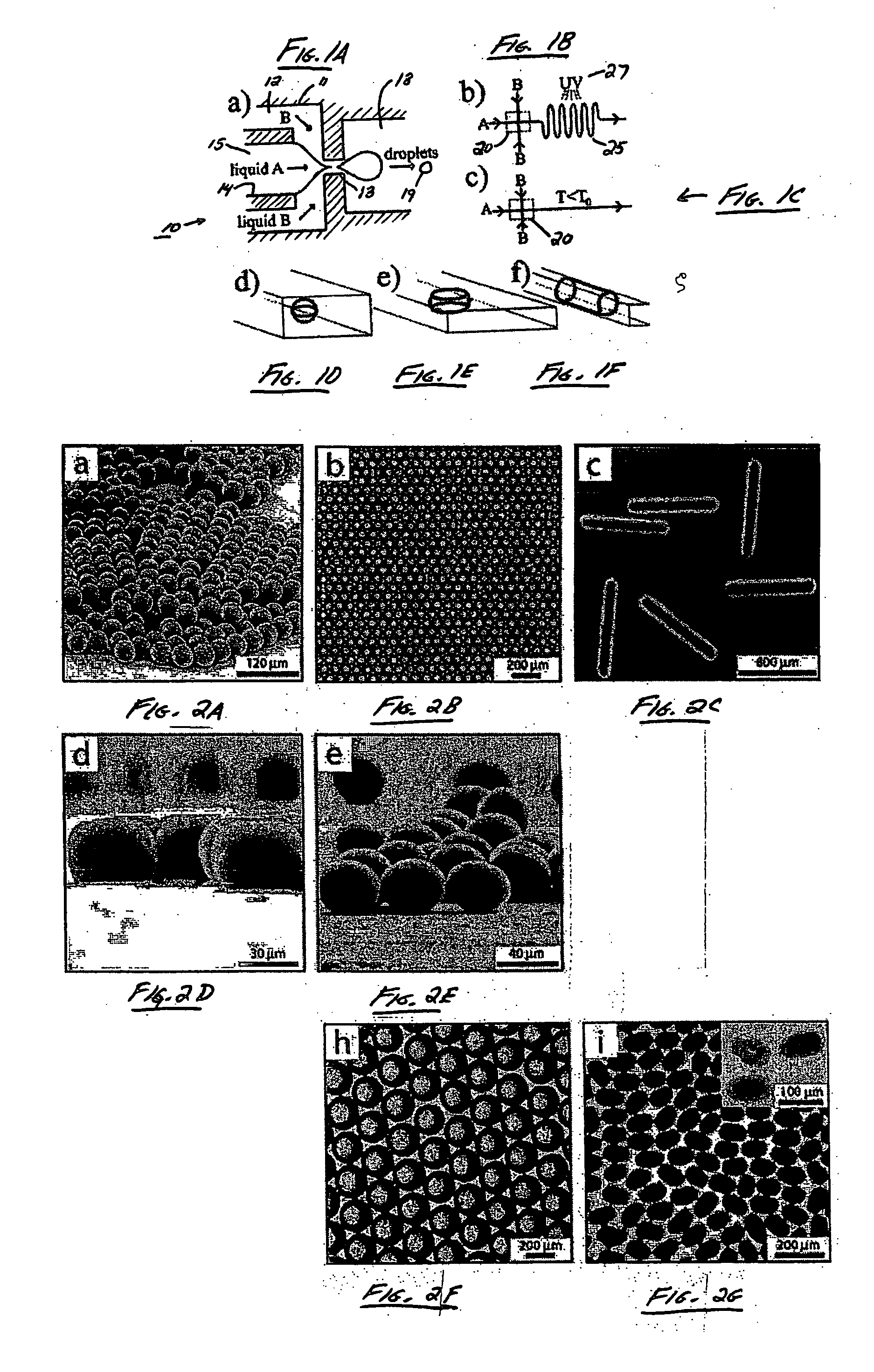
[0081] The monodisperse droplets formed in the MFFD described in Example 1 were used to prepare particles in this example by solidifying these drops, either photochemically or thermally. FIG. 1B is a schematic diagram showing the polymerization of monomer droplets, and FIG. 1C is a schematic diagram showing the cooling of hydrogels or metals below their gelation or melting temperature, respectively. In these figures, the dashed rectangles 20 mark the position of the flow-focusing device shown in FIG. 1A. The channels used for photochemical cross-linking were also lengthened in this example to allow for generally longer durations of exposure of the droplets to UV light. This is shown in FIG. 1B as a “wavy” channel 5, eliminated by UV light source 27.

[0082] In various experiments, polymerization was used to produce monodisperse, solid, shaped particles from tripropyleneglycol diacrylate (“TPGDA”), dimethacrylate oxypropyldimethylsiloxane (“DMOS”), divinyl benzene (“DVB”), ethylenegly...

example 3

[0091] In this example, non-spherical particles were produced using the MFFD described in Example 1. In some experiments, agarose disks and bismuth alloy ellipsoids were produced using methods similar to those described in Example 2, for example, by introducing a fluidic droplet having a volume such that the fluidic droplet, within the outlet channel, was not able to form a spherical shape, and instead, formed a non-spherical shape. For example, a rod, a disk, an ellipsoid, etc. Other examples of non-spherical particles are described in this example, and are illustrated in FIG. 2.

[0092]FIGS. 2A-2G are a series of optical microscopy images of polyTPGDA particles, some of which are non-spherical: microspheres (FIG. 2A), crystal of microspheres (FIG. 2B), rods (FIG. 2C), disks (FIG. 2D), and ellipsoids (FIG. 2E). Rods were prepared having aspect ratios as large as 1:12 FIG. 1C). The ellipsoid particles were formed at relatively high flow rates of the continuous phase in the wavy chann...


PUM

PropertyMeasurementUnit
Lengthaaaaaaaaaa
Lengthaaaaaaaaaa
Lengthaaaaaaaaaa

Abstract

The present invention generally relates to systems and methods of forming particles and, in certain aspects, to systems and methods of forming particles that are substantially monodisperse. Microfluidic systems and techniques for forming such particles are provided, for instance, particles may be formed using gellation, solidification, and/or chemical reactions such as cross-linking, polymerization, and/or interfacial polymerization reactions. In one aspect, the present invention is directed to a plurality of particles having an average dimension of less than about 500 micrometers and a distribution of dimensions such that no more than about 5% of the particles have a dimension greater than about 10% of the average dimension, which can be made via microfluidic systems. In one set of embodiments, at least some of the particles may comprise a metal, and in certain embodiments, at least some of the particles may comprise a magnetizable material. In another set of embodiments, at least some of the particles may be porous. In some embodiments, the invention includes non-spherical particles. Non-spherical particles may be formed, for example, by urging a fluidic droplet into a channel having a smallest dimension that is smaller than the diameter of a perfect mathematical sphere having a volume of the droplet, and solidifying the droplet, and/or by exposing at least a portion of a plurality of particles to an agent able to remove at least a portion of the particles.

Description

RELATED APPLICATIONS [0001] This application claims the benefit of U.S. Provisional Patent Application Ser. No. 60 / 659,046, filed Mar. 4, 2005, entitled “Systems and Methods of Forming Particles,” by Garstecki, et al., which is incorporated herein by reference.FEDERALLY SPONSORED RESEARCH [0002] Various aspects of the present invention were sponsored by the NIH, Grant Nos. GM65364 and GM067445, the Department of Energy, Grant No. DE-FG02-OOER45852, DARPA, and the NSF, Grant Nos. DMR-9809363 and DMR-0213805. The U.S. Government may have certain rights in the invention.FIELD OF INVENTION [0003] The present invention generally relates to systems and methods of forming particles and, in certain aspects, to systems and methods of forming particles that are substantially monodisperse. In some cases, the present invention generally relates to methods for producing particles having a predetermined shape, size, and / or composition, and in some instances, the present invention relates to a mic...

Claims


Application Information

Patent Timeline
IPC IPC(8): B32B1/00B22F1/06
CPCB01F3/0807B01F13/0062B01J19/0093Y10T428/2982B01J2219/00873B22F1/0007B22F9/06B01J19/06B01F23/41B01F33/3011B22F1/06
Inventor GARSTECKI, PIOTRWEIBEL, DOUGLAS B.GITLIN, IRINATAKEUCHI, SHOJIXU, SHENGQINGNIE, ZHIHONGSEO, MIN SEOKLEWIS, PATRICK C.KUMACHEVA, EUGENIASTONE, HOWARD A.WHITESIDES, GEORGE M.
Owner PRESIDENT & FELLOWS OF HARVARD COLLEGE
Why Eureka
Try Eureka