Method and system for optimizing left-heart lead placement

a technology of pacing leads and optimizing leads, which is applied in the field of optimizing the placement of leads, can solve the problems of inconvenient prediction, incomplete and complex implant procedures, and achieve the effect of improving the placement of pacing leads

Inactive Publication Date: 2007-03-08
STEREOTAXIS
View PDF99 Cites 146 Cited by
  • Summary
  • Abstract
  • Description
  • Claims
  • Application Information

AI Technical Summary

Benefits of technology

[0004] Generally, embodiments of the methods of the present invention provide for improved placement of pacing leads. Various embodiments of the methods of the present invention optimize lead placement by providing various measures for predicting lead implantation success, and

Problems solved by technology

Left heart lead placement is fraught with difficulties including accessing the Coronary Sinus, sub-selecting veins, and finding an implant site in the coronary venous structure that provides an ideal pacing response without phrenic nerve stimulation.
The structure of the corona

Method used


Image

  • Method and system for optimizing left-heart lead placement
  • Method and system for optimizing left-heart lead placement
  • Method and system for optimizing left-heart lead placement

Examples


Embodiment Construction

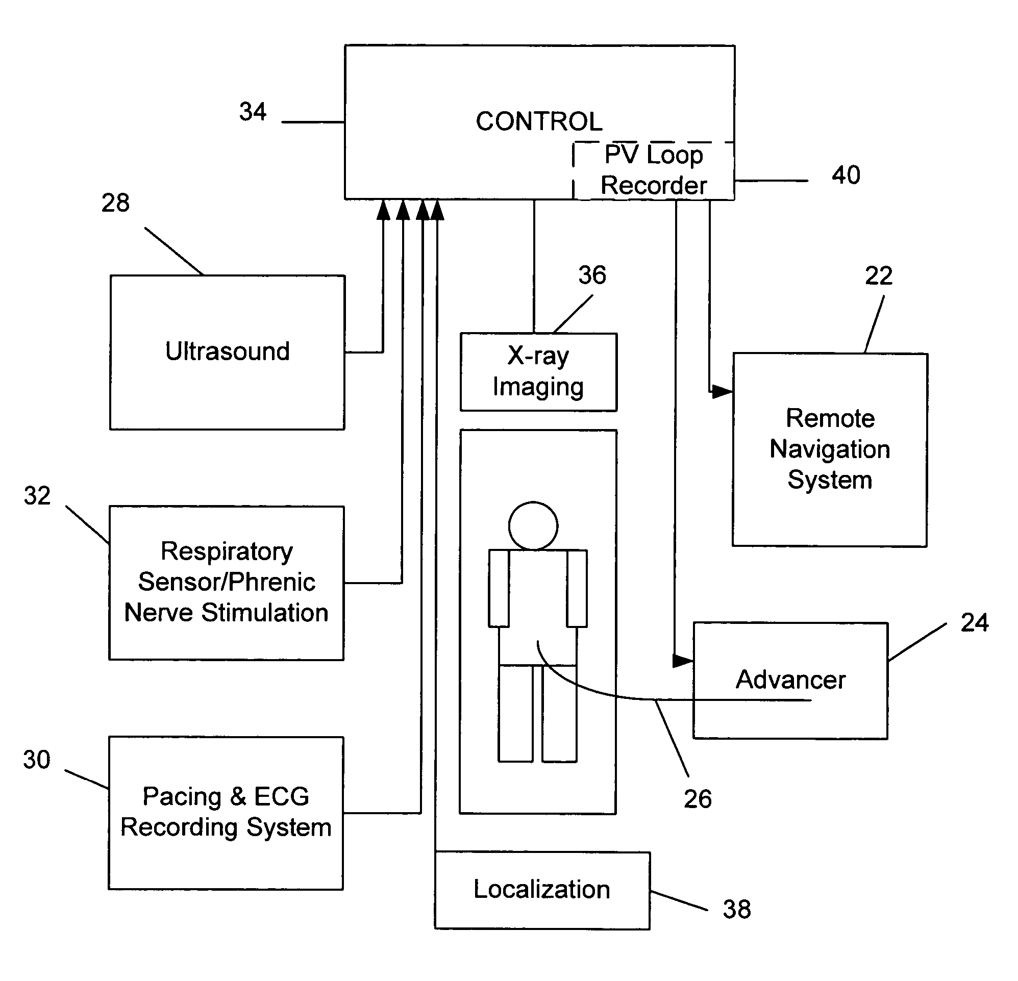
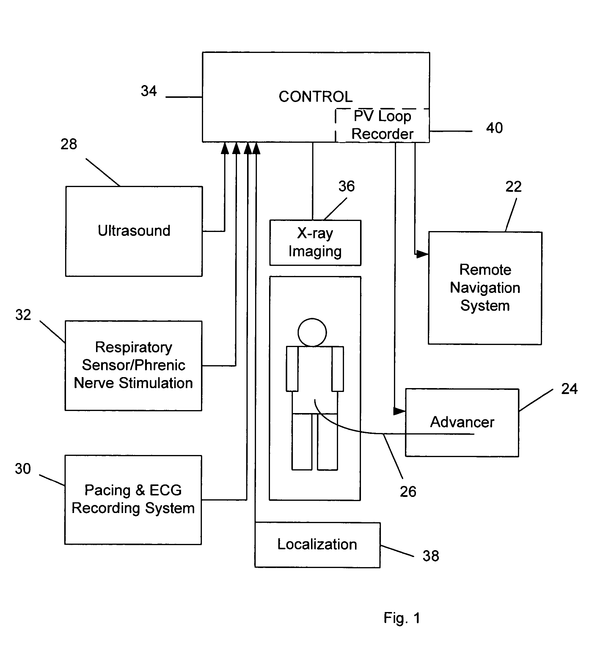
[0008] This invention relates to the navigation and placement of pacing leads in the heart. Embodiments of this invention provide a system for, and methods of, optimally placing such pacing leads. A preferred embodiment of a system for placing pacing leads in accordance with this invention is indicated generally as 20 in FIG. 1. The system 20 comprises a remote navigation system 22. This remote navigation system 22 preferably has the ability to remotely orient the distal end of a medical device 24 such as a guide wire or catheter, and advance the end to a selected location. One example of such a remote navigation system is the Niobe® remote magnetic navigation system available from Stereotaxis, Inc., St. Louis, Mo., which uses external source magnets to create a magnetic field in a selected direction in the operating region in a subject. This magnetic field acts on a magnetically responsive element at the distal end of the medical device to orient the medical device in a selected di...


PUM


Abstract

A system for identifying locations for pacing the heart, the system comprising a pacing electrode, a remote navigation system for positioning the pacing electrode at each of a plurality of locations; a system for determining Pressure-Volume loop data resulting from pacing at each location; an ECG system, a phrenic nerve stimulation detection system, and a means of identifying at least one preferred location based upon at least the Pressure-Volume loop, ECG, and phrenic nerve stimulation data at each location. A method of identifying locations for pacing the heart, the method comprising: navigating a pacing electrode to each of a plurality of locations in the heart; pacing the heart at each of the plurality of locations; and assessing the effectiveness of the pacing at each location by measuring cardiac blood flow and cardiac wall strain.

Description

CROSS REFERENCE TO RELATED APPLICATION [0001] This application is a Continuation In Part of and claims priority from U.S. patent application Ser. No. ______, filed Aug. 24, 2005, entitled Methods and Apparatus for Steering Medical Devices in Body Lumens [Attorney Docket Number 5236-000602], which claims priority from U.S. Provisional Patent Application Ser. No. 60 / 604,101, filed Aug. 24, 2004, Methods and Apparatus for Steering Medical Devices in Body Lumens, and U.S. patent application Ser. No. 10 / 448,273, filed May 29, 2003, entitled Remote Control of Medical Devices Using a Virtual Device Interface; which claims priority of U.S. Provisional Patent Application No. 60 / 401,670, filed Aug. 6, 2002, entitled, Method and Apparatus for Improved Magnetic Surgery Employing Virtual Device Interface, and of U.S. Provisional Patent Application Ser. No. 60 / 417,386, filed Oct. 9, 2002, Method and Apparatus for Improved Magnetic Surgery Employing Virtual Device Interface, the disclosures of all...

Claims


Application Information

Patent Timeline
IPC IPC(8): A61B5/05
CPCA61B5/0452A61B5/06A61B8/565A61B8/0833A61B6/12A61B5/062A61B5/349
Inventor VISWANATHAN, RAJU R.FLICKINGER, WILLIAM
Owner STEREOTAXIS
Why Eureka
Try Eureka