Heater unit and semiconductor manufacturing apparatus including the same

Inactive Publication Date: 2007-03-15
SUMITOMO ELECTRIC IND LTD
View PDF4 Cites 14 Cited by
  • Summary
  • Abstract
  • Description
  • Claims
  • Application Information

AI Technical Summary

Benefits of technology

[0012] In view of such conditions of the prior art, an object of the present invention is to provide a ceramic heater that can attain more uniform heater temperature distribution from the start to the end of cooling and to provide a semiconductor manufacturing apparatus having the h

Problems solved by technology

Further, increase in the rate of temperature increase and the rate of cooling is also required.
The apparatus, however, becomes expensive as passage 15 must be fabricated through machine processing, and the apparatus cannot be provided at a low cost.
Further, dependent on the material of plate-shaped

Method used


Image

  • Heater unit and semiconductor manufacturing apparatus including the same
  • Heater unit and semiconductor manufacturing apparatus including the same
  • Heater unit and semiconductor manufacturing apparatus including the same

Examples


Example

EXAMPLE

[0088] As shown in FIG. 5, a ceramic heater including a heater body 2 formed of ceramic base member 2a, heater body circuit 2b and insulating layer 2c, and cooling module 3, which is brought into contact with heater body 2 for cooling heater body 2, was fabricated.

[0089] As base member 2a of heater body 2, an aluminum nitride (AlN) sintered body having the diameter of 330 mm and thickness of 12 mm was used. On a rear surface of base member 2a, a conductive paste was applied by screen-printing and then fired, to form heater body circuit 2b, and further, insulating layer 2c for protecting heater body circuit 2b was formed. Considering matching of thermal expansion coefficient with ceramics, the conductive paste was prepared using tungsten powder as the metal powder, with oxide powder, a binder and a solvent mixed as needed. As for insulating layer 2c, a paste prepared by adding an organic solvent and a binder to glass powder was applied by screen-printing and then fired, to f...

Example

Example 1

[0096] In addition to the cooling module (CP1), a cooling module (CP2) formed only of a plate-shaped structure 4 of an aluminum disk having the diameter of 330 mm and thickness of 10 mm was prepared. Cooling test was done on ceramic heaters having these two different cooling modules, and the results are as shown in Table 1 below. The reference for determining “cooling performance evaluation” in Tables 1 to 4 are as follows.

[0097] A: necessary cooling time from 240° C. to 150° C. is shorter than 90 sec., and necessary cooling time from 180° C. to 120° C. is shorter than 60 sec.

[0098] B: necessary cooling time from 240° C. to 150° C. is shorter than 118 sec., and necessary cooling time from 180° C. to 120° C. is shorter than 88 sec.

[0099] C: necessary cooling time from 240° C. to 150° C. is shorter than 146 sec., and necessary cooling time from 180° C. to 120° C. is shorter than 116 sec.

[0100] D: necessary cooling time from 240° C. to 150° C. is not shorter than 146 sec....

Example

Example 2

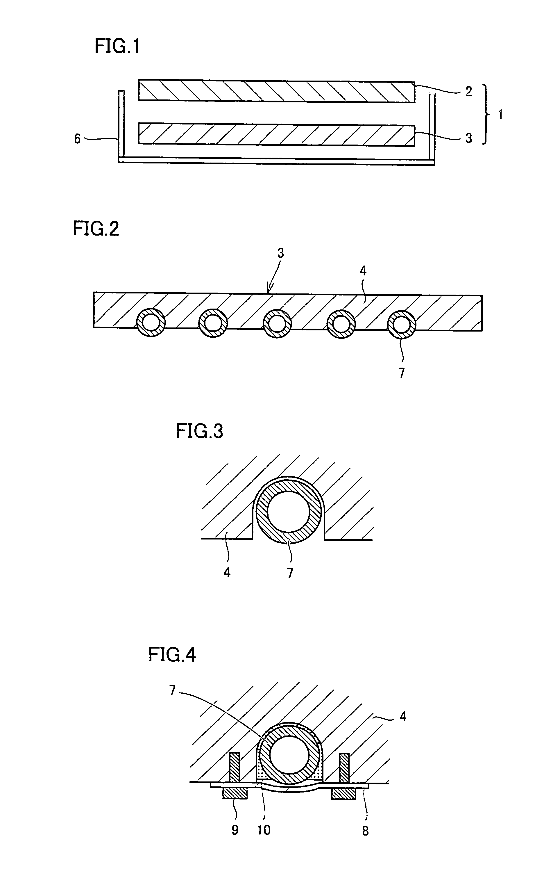
[0101] In addition to the cooling module (CP1) described above, three cooling modules (CP3 to CP5) were formed in which only the depth of trenches formed in plate-shaped structure 4 of aluminum disk were made different. Cooling test was done on ceramic heaters having these four different cooling modules, and the results are as shown in Table 2 below. As can be seen from Table 2, good cooling characteristics were attained when the depth of the trench was made the same or deeper than the outer radius (3 mm) of the pipe. TABLE 2Cooling from 240° C. to 150° C.Cooling from 180° C. to 120° C.Trench depththermalcoolingcoolingthermalcoolingcoolingof plate-shapeduniformitytimeperformanceuniformitytimeperformancestructure(° C.)(sec)evaluation(° C.)(sec)evaluationCP15 mm23.980A8.654ACP3no trench25.2126C10.299CCP42 mm25.798B10.771BCP57 mm23.678A8.751A


PUM

PropertyMeasurementUnit
Lengthaaaaaaaaaa
Diameteraaaaaaaaaa
Diameteraaaaaaaaaa

Abstract

A ceramic heater attaining more uniform temperature distribution from the start to the end of cooling is provided. Further, in a cooling module used for cooling the heater, liquid leakage during use is prevented, degradation in cooling capability is prevented and the performance is maintained for a long period of use, and the manufacturing cost of the module is decreased. The ceramic heater includes a ceramic heater body and a cooling module cooling the heater body, and the cooling module has a structure formed by arranging a pipe in a trench formed in a plate-shaped structure.

Description

[0001] This nonprovisional application is based on Japanese Patent Application No. 2005-263183 filed with the Japan Patent Office on Sep. 12, 2005, the entire contents of which are hereby incorporated by reference. BACKGROUND OF THE INVENTION [0002] 1. Field of the Invention [0003] The present invention relates to a ceramic heater provided with a heater body formed of ceramics on which an object of processing is placed for heat treatment and a cooling module including plate-shaped structure for cooling the heater body, as well as to a semiconductor manufacturing apparatus having the ceramic heater mounted thereon. [0004] 2. Description of the Background Art [0005] Conventionally, in the process of manufacturing a semiconductor, a semiconductor substrate (wafer) as an object of processing is subjected to various processes including film formation and etching. In a semiconductor manufacturing apparatus used for performing such processes on the semiconductor substrate, a ceramic heater...

Claims


Application Information

Patent Timeline
IPC IPC(8): H05B3/68
CPCH05B3/143H01L21/67109
Inventor AWAZU, TOMOYUKIMIKUMO, AKIRANATSUHARA, MASUHIRONAKATA, HIROHIKO
Owner SUMITOMO ELECTRIC IND LTD
Why Eureka
Try Eureka