
Semiconductor device and manufacturing method of the same

a semiconductor and manufacturing method technology, applied in the field of semiconductor devices, can solve the problems of increased contact resistance, increased wafer manufacturing cost, and increased contact resistan

Inactive Publication Date: 2007-03-15
KK TOSHIBA
View PDF3 Cites 10 Cited by
  • Summary
  • Abstract
  • Description
  • Claims
  • Application Information

AI Technical Summary

Problems solved by technology

However, manufacturing of a SOI wafer with the BOX film set to less than 60 Angstrom in thickness and the SOI film set to less than 300 Angstrom in the SOI substrate requires highly accurate control of wafer manufacturing process, thereby leading to increase in wafer manufacturing cost, which is a large obstacle to achievement of an excellent FBC.
If the thickness of the SOI film is too small, when a contact is formed, not only electric short-circuit is likely to occur between the contact and plate potential but also contact resistance is increased, which is a problem to be solved.
Although the SOI film can be thinned uniformly, if the SOI film is thinned to about 20 nm, the ΔVth is decreased, so that an intention of improving performance using a device under a fully depleted condition by thinning the SOI film is not achieved.
Additionally, if the BOX film is thinned extremely, diffusion capacitance increases so that sharing of process with a logic section, which is a large advantage of the FBC, becomes impossible.

Method used


Image

  • Semiconductor device and manufacturing method of the same
  • Semiconductor device and manufacturing method of the same
  • Semiconductor device and manufacturing method of the same

Examples


first embodiment

(1) First Embodiment

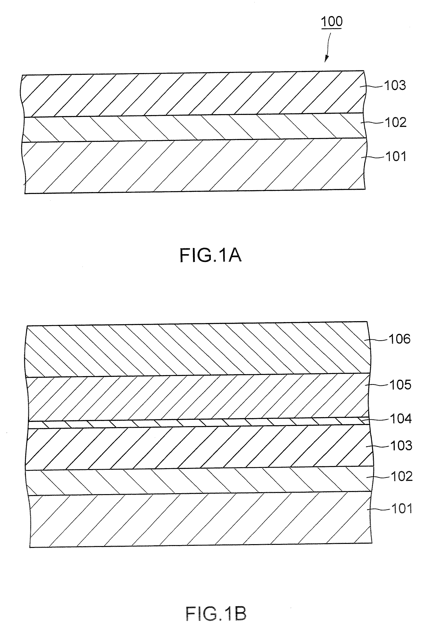
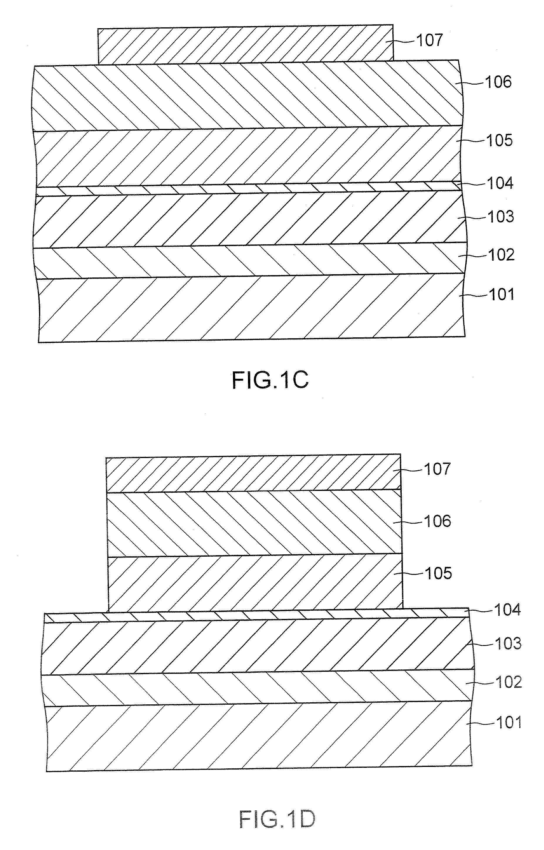
[0035] An example of first manufacturing process for manufacturing a semiconductor device according to a first embodiment of the present invention will be described with reference to FIGS. 1A-1L.

[0036] First, a SOI substrate 100 in which buried oxide film (BOX film) 102 in the thickness of 250 Angstrom is provided on a silicon semiconductor base material 101 and silicon film (SOI film) 103 in the thickness of 1500 Angstrom is formed thereon is prepared (FIG. 1A).

[0037] Next, thermally-oxidized film 104 about 20 Angstrom thick is formed by heating the SOI substrate 100 in oxidation atmosphere and subsequently, SiN film 105 in the thickness of 1700 Angstrom is deposited and further, boro silicate glass (BSG) film 106 in the thickness of 3000 Angstrom is deposited (FIG. 1B).

[0038] Next, resist pattern is formed for forming a device region of a desired pattern. That is, photo resist 107 is applied on its entire surface and the resist pattern is formed by patternin...


PUM


Abstract

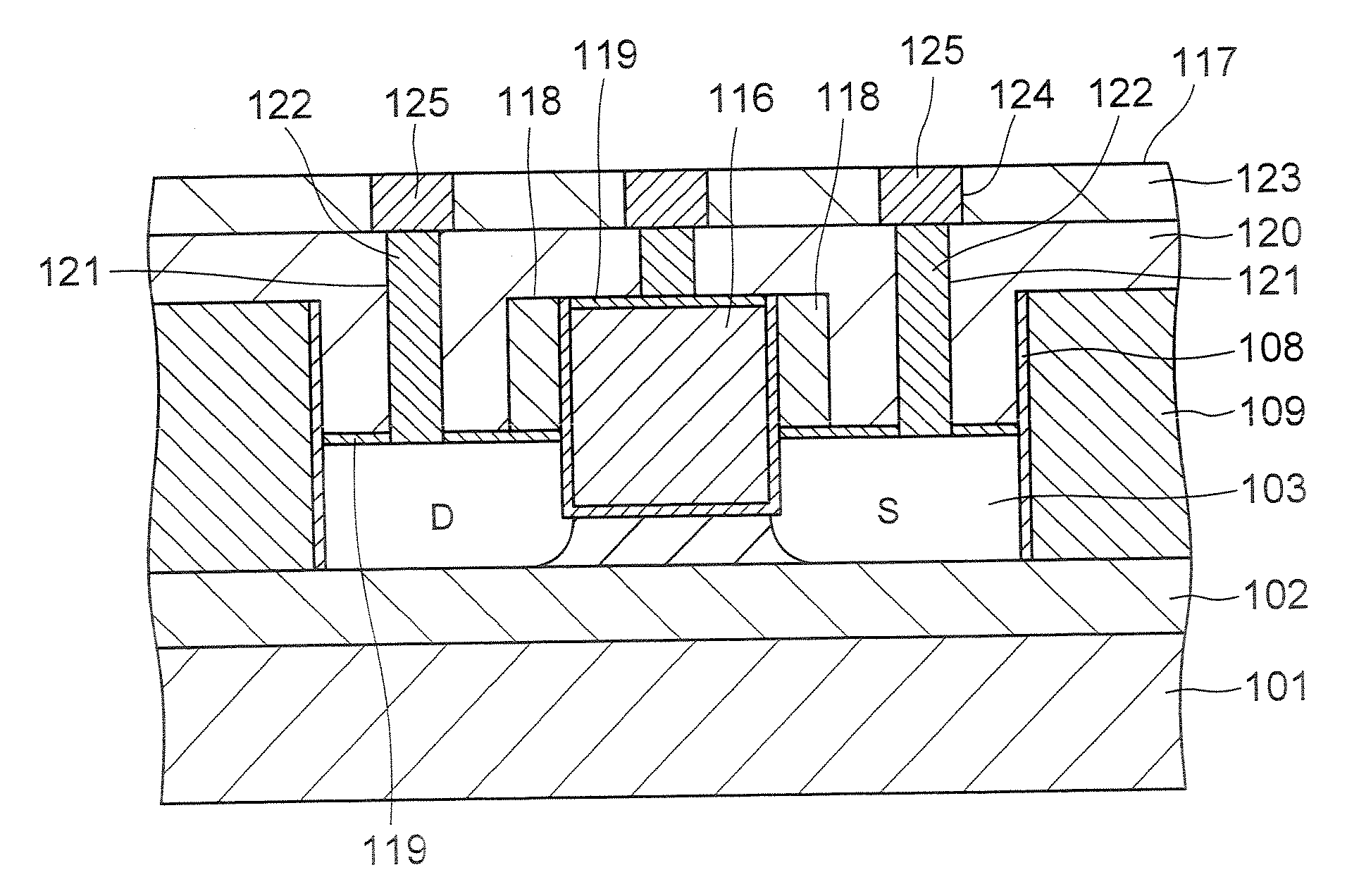
A semiconductor device comprises: a channel region of a transistor formed in a predetermined region of silicon layer formed on insulation film; a gate electrode formed on the channel region via gate insulation film; and source / drain regions formed in the silicon layer thicker than said channel region located out of the channel region, wherein the transistor is a memory element constituting the channel region as a floating body cell.

Description

CROSS REFERENCE TO RELATED APPLICATION [0001] This application is based upon and claims the benefit of priority from the prior Japanese Patent Applications No. 2005-259494, filed on Sep. 7, 2005; the entire contents of which are incorporated herein by reference. BACKGROUND OF THE INVENTION [0002] The present invention relates to a semiconductor device and more particularly to a semiconductor memory device using a silicon on insulator (SOI) substrate. The present invention also relates to a manufacturing method of the semiconductor device. [0003] The SOI substrate in which an insulation film (buried insulation film) is provided on a silicon substrate and a silicon layer is provided on the insulation film has been known in, for example, Japanese Patent Application Laid-Open Publication No. 2001-298171 and Japanese Patent Application Laid-Open Publication No. 5-257356(1993). [0004] A semiconductor memory device having a floating body cell (FBC) memory cell with a portion corresponding ...

Claims


Application Information

Patent Timeline
IPC IPC(8): H01L27/12
CPCH01L27/108H01L27/10802H01L29/66621H01L29/78618H01L29/66772H01L29/7841H01L29/66659H10B12/20H10B12/00
Inventor MORIKADO, MUTSUO
Owner KK TOSHIBA
Learn More