Electro-acoustic transducer device

Inactive Publication Date: 2007-03-15
HITACHI LTD
View PDF2 Cites 19 Cited by
  • Summary
  • Abstract
  • Description
  • Claims
  • Application Information

AI Technical Summary

Benefits of technology

[0012] According to the present invention, it is possible to monitor the quantity of the electricity in the charge-storage layer, and to suppress drift in device characteristics, which is the main cause for variation in device se

Problems solved by technology

Notwithstanding the above, in reality, the insulating layer is in unstable electrification state, and a quantity of electrification undergoes a drift while the insulating layer is in use.
This creates a problem that electro-acoustic conversion efficiency, that is, the most fundamental property of the electro-acoustic transducer device undergoes a drift when the DC bias voltage is kept constant.
Even if the electro-acoustic conversion efficiency is at a satisfactory level in magnitude, difficulty in stabilizing the electro-acoustic conversion efficiency will present a major stumbling block to commercial application thereof as the transducer, as is evident from the case of the Rochelle salt, pre

Method used


Image

  • Electro-acoustic transducer device
  • Electro-acoustic transducer device
  • Electro-acoustic transducer device

Examples


Embodiment Construction

[0028] Embodiments of the invention are described hereinafter with reference to the accompanying drawings.

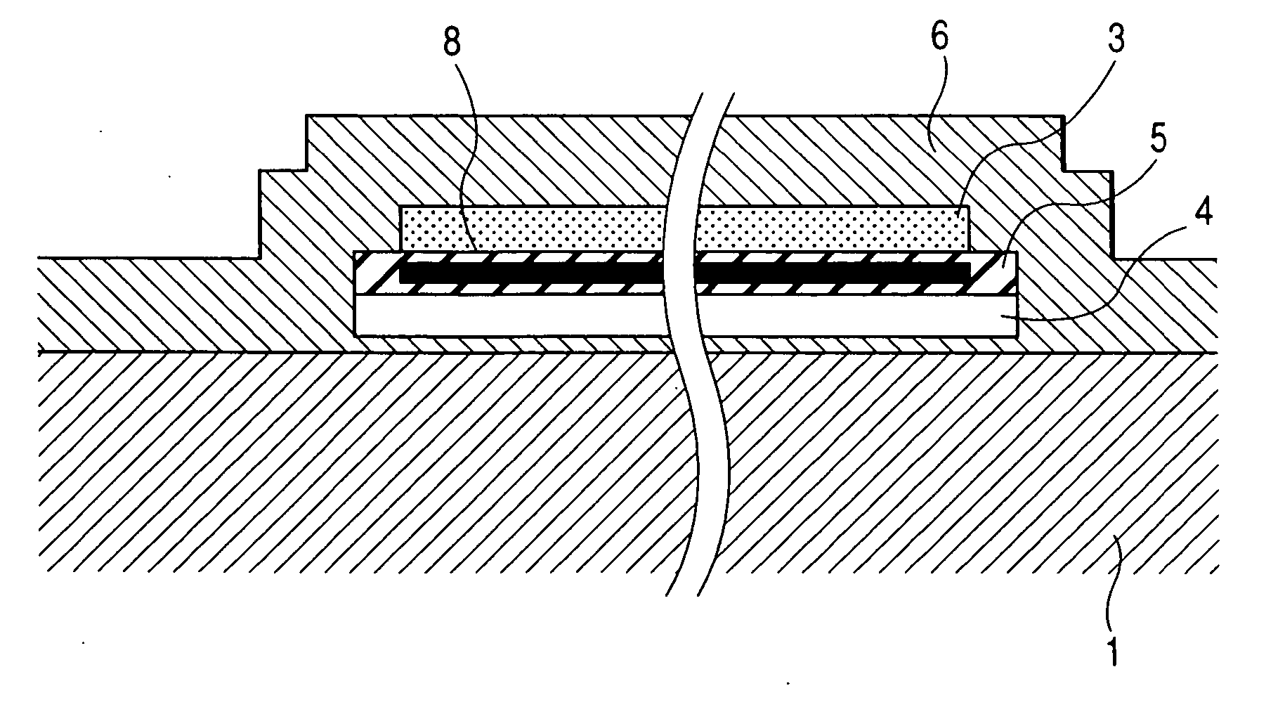
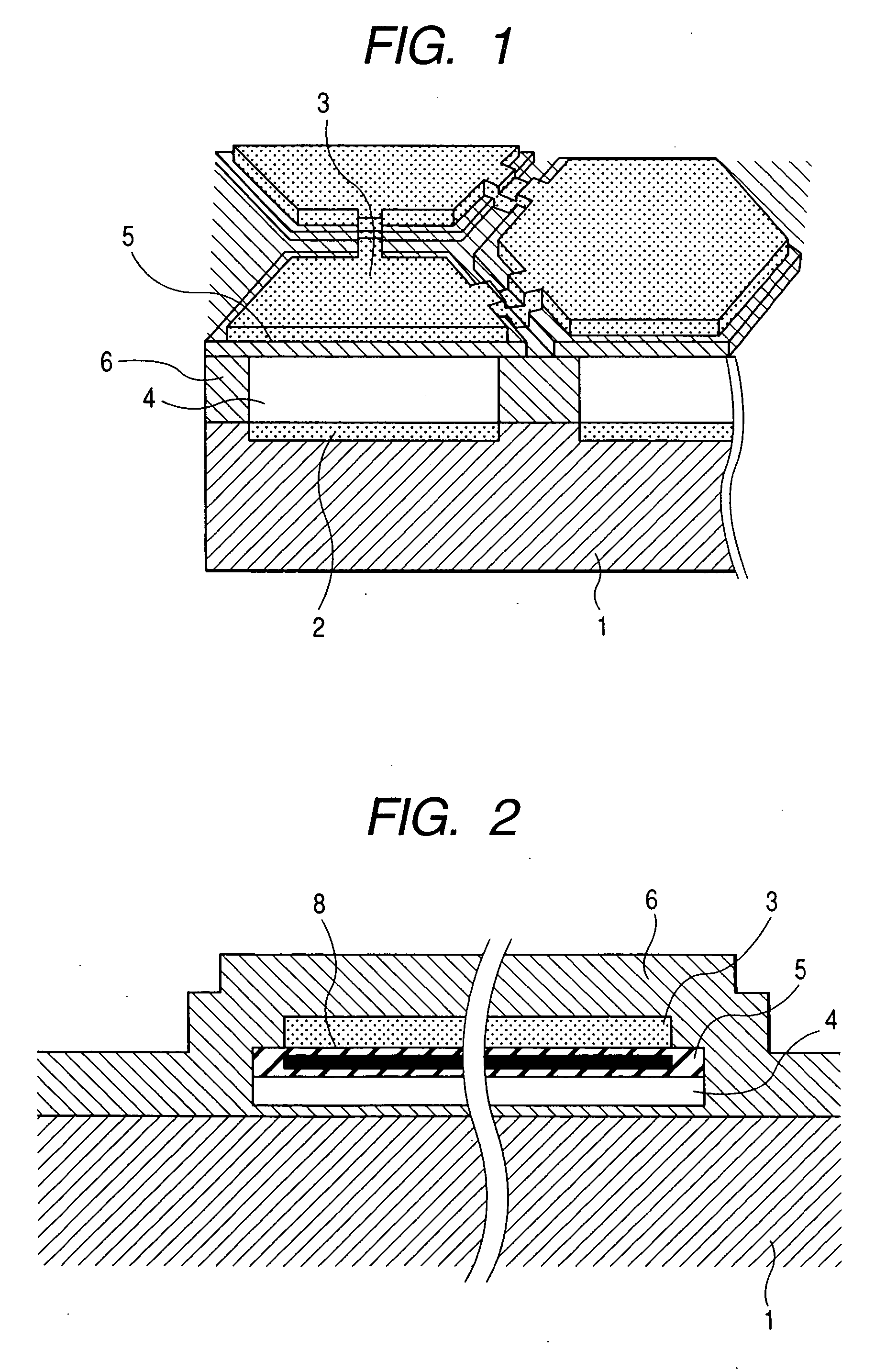
[0029]FIG. 2 is a sectional view showing one embodiment of an electro-acoustic transducer device according to the invention, using silicon as a base material. The electro-acoustic transducer device comprises respective layers sequentially disposed in the following order from the bottom, including an n-type silicon (Si) substrate 1 doubling as a lower electrode 2, a first silicon compound layer, a void layer 4, a second silicon compound layer 5, an upper electrode 3 made of aluminum, and a first silicon compound layer 6. As for a thickness of each of the layers according to the present embodiment, the first silicon compound layer positioned under the void layer is 30 nm in thickness, the void layer is 100 nm in thickness, the second silicon compound layer is 200 nm in thickness, the upper electrode is 200 nm in thickness, and the first silicon compound layer positioned on top of...


PUM


Abstract

In a semiconductor diaphragm type electro-acoustic transducer device having no necessity for a DC bias voltage applied as a result of a charge-stored layer being provide between electrodes, electro-mechanical conversion efficiency undergoes a change owing to time-dependent change in a quantity of stored electricity due to leakage of charge, and so forth. As for sensitivity of signal reception, provided by an ultrasonic array-transducer made up of the electro-acoustic transducer devices each as a basic unit, not only a main beam sensitivity undergoes drift as a result of drift in the electromechanical conversion efficiency, but also there result deterioration in an acoustic S/N ratio, and deterioration in directionality of an ultrasonic beam. In order to resolve those problems, there is provided an electro-acoustic transducer device comprising a first electrode formed on top of, or inside a substrate, a thin film using silicon or a silicon compound as a base material thereof, provided on top of the substrate, a second electrode formed on top of, or inside the thin film, a void layer provided between the first electrode and the second electrode, a charge-stored layer for storing charge given by the first electrode and the second electrode, provided between the first electrode and the second electrode, and a source electrode and a drain electrode, for measuring a quantity of electricity stored in the charge-storage layer.

Description

CLAIM OF PRIORITY [0001] The present application claims priority from Japanese application JP 2005-255817 filed on Sep. 5, 2005, the content of which is hereby incorporated by reference into this application. FIELD OF THE INVENTION [0002] The present invention relates to a transducer for transmitting and receiving ultrasonic waves and in particular, to a diaphragm-based ultrasonic transducer device using silicon as a base material. BACKGROUND OF THE INVENTION [0003] Progress made in such piezoelectric materials having large and stable piezoelectricity as represented by a PZT (lead zirconate titanate) based piezoelectric ceramic, a piezoelectric transducer using the same, and a semiconductor transmit-receive circuit highly adaptable to the piezoelectric transducer has contributed to remarkable development and widespread use of an ultrasonic technology during the latter half of the 20th century. In the early years of the 20th century, the human race started an attempt to transmit and ...

Claims


Application Information

Patent Timeline
IPC IPC(8): H01L41/09
CPCH04R19/005B06B1/0292
Inventor AZUMA, TAKASHIUMEMURA, SHIN-ICHIRONAGATA, TATSUYAFUKUDA, HIROSHIMACHIDA, SHUNTAROMINE, TOSHIYUKI
Owner HITACHI LTD
Why Eureka
Try Eureka