
System and method for controlling antenna pattern

Inactive Publication Date: 2007-03-15
KYOCERA CORP
View PDF13 Cites 45 Cited by
  • Summary
  • Abstract
  • Description
  • Claims
  • Application Information

AI Technical Summary

Benefits of technology

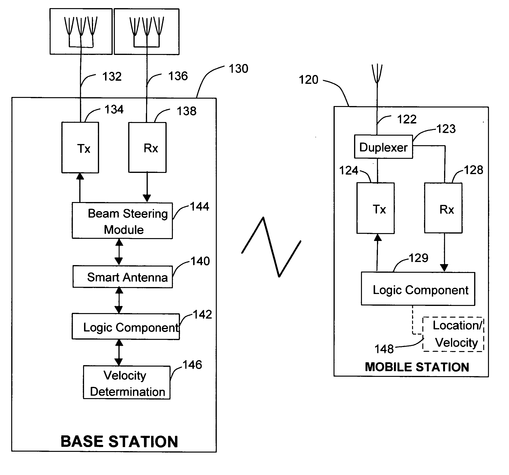
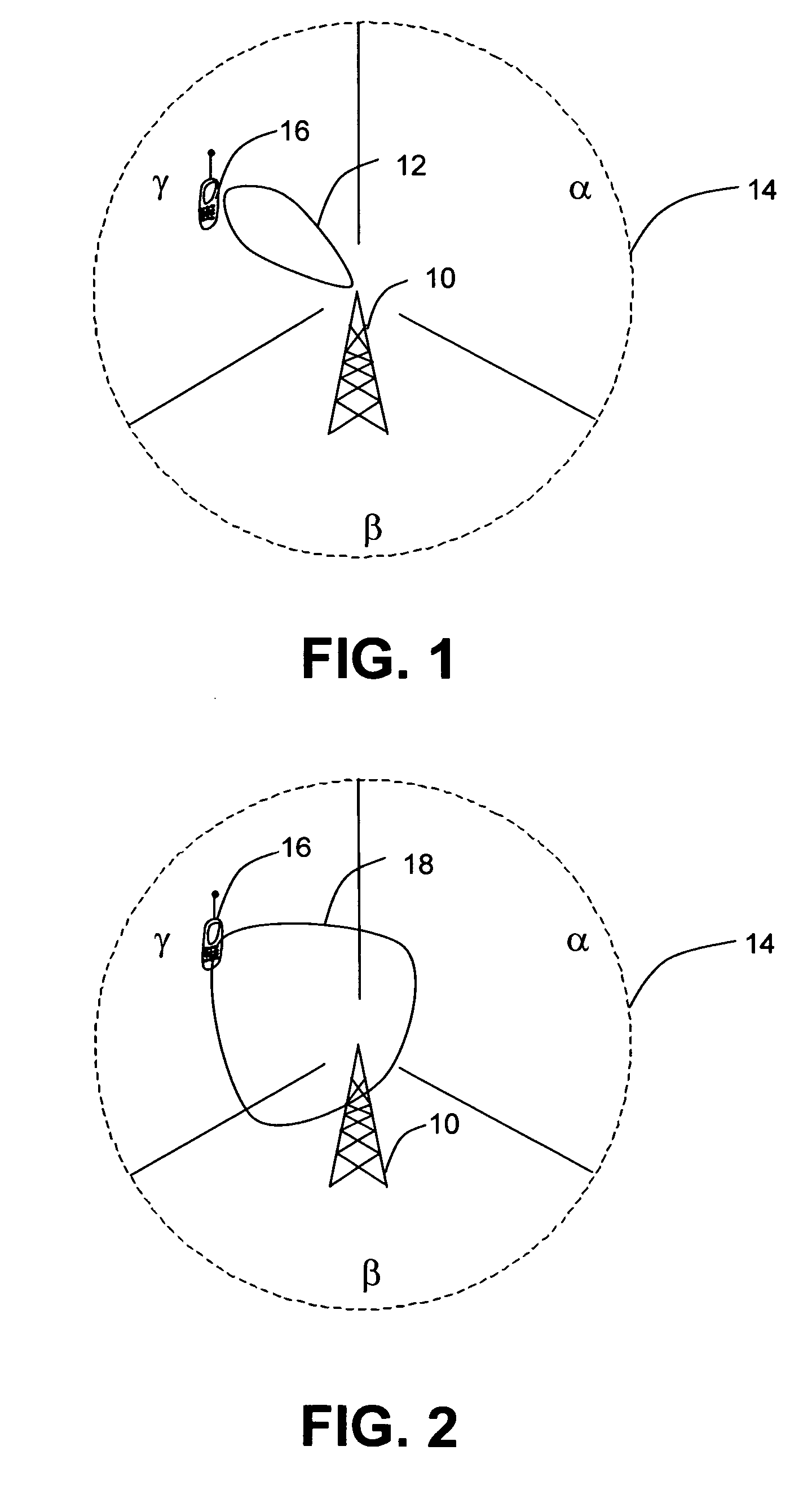
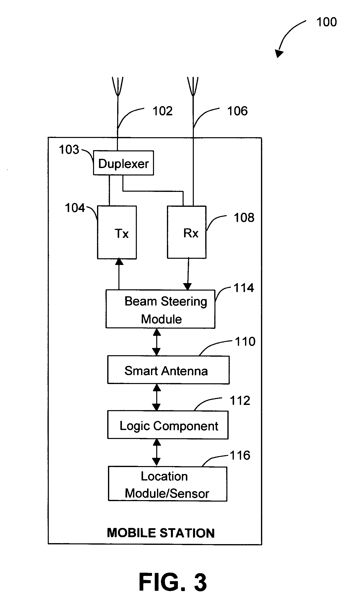
[0010] Typically, the operating antenna pattern is broader than the initial antenna pattern when the mobile station exceeds a particular speed. By way of example and not of limitation, the operating antenna pattern coverage increases due to increasing speed of the mobile station, and the operating antenna pattern coverage decreases due to decreasing speed of the mobile station. For example, when the mobile station is at a driving speed, the operating antenna pattern may be omni-directional. The communication system may be situated on the mobile station, the base station, or a combination thereof. Additionally, the communication system may be embodied in an integrated circuit, a processor, or a combination of such devices.

Problems solved by technology

In mobile communication systems, capacity and performance are usually limited by multipath and co-channel interference.
The result is degradation in signal quality when they are combined at the receiver due to the phase mismatch.
However, there are a number of limitations to smart antennas.
These include performance degradation when the mobile station is in motion.
More particularly, at driving speeds and pedestrian speeds, performance degradation is caused by inadequate beam steering.
Performance degradation is caused by the smart antenna's limitations.
The smart antenna's beam steering is too focused, and does not easily accommodate movement of the mobile station.
As a result the mobile station may drop calls.
Solutions such as increasing processor speed fail to solve these smart antenna limitations because the problem revolves around measurements needed to collect the data required for beam steering.
However, when the mobile station is in motion, the time needed to make these measurements with the required accuracy is not available.
The resulting measurement data is less accurate or is incomplete resulting in performance degradation of the smart antenna.
Thus, when the mobile station is moving faster than the rate at which the smart antenna measurements can be completed, performance is degraded.

Method used


Image

  • System and method for controlling antenna pattern
  • System and method for controlling antenna pattern
  • System and method for controlling antenna pattern

Examples


Embodiment Construction

[0018] Persons of ordinary skill in the art will realize that the following description is illustrative and not in any way limiting. Other embodiments of the claimed subject matter will readily suggest themselves to such skilled persons having the benefit of this disclosure. It shall be appreciated by those of ordinary skill in the art that the systems described hereinafter may vary as to configuration and as to details. Additionally, the method may vary as to details, order of the actions, or other variations without departing from the illustrative method disclosed herein.

[0019] Referring to FIG. 1 there is shown an illustrative diagram of a base station having a smart antenna module that generates an initial antenna pattern. The illustrative base station 10 has a smart antenna module (not shown) that generates an illustrative initial antenna pattern 12. This illustrative initial antenna pattern 12 is related to base station transmission, base station reception, or a combination t...


PUM


Abstract

A communication system and method for controlling an antenna pattern is disclosed. The communication system may be situated on a mobile station, a base station, or a combination thereof. The communication system comprises a smart antenna module, a speed sensor, and a beam steering module. The smart antenna module may be situated on the mobile station, the base station, or a combination thereof. The smart antenna module generates at least one initial antenna pattern. The speed sensor is configured to determine a speed of a mobile station. The beam steering module generates an operating antenna pattern that is different from the initial antenna pattern. The operating antenna pattern is affected by changes in the speed of the mobile station.

Description

FIELD OF THE INVENTION [0001] This invention relates to an apparatus and method for controlling antenna pattern. More particularly, the invention relates to control of the antenna pattern as a function of the speed of a mobile station. BACKGROUND OF THE INVENTION [0002] In mobile communication systems, capacity and performance are usually limited by multipath and co-channel interference. Multipath is a condition which arises when a transmitted signal undergoes reflection from various obstacles in the propagation environment. The multipath signals follow different paths and have different phases when they are arrive at the receiver. The result is degradation in signal quality when they are combined at the receiver due to the phase mismatch. [0003] Smart antennas enable a higher capacity in wireless networks by effectively reducing multipath and co-channel interference. Smart antennas focus the radiation in the preferred direction and adjusts itself to changing traffic conditions or s...

Claims


Application Information

Patent Timeline
IPC IPC(8): H01Q3/00H04Q7/20H04W16/28
CPCH01Q3/2605H04W16/28H04B7/0617
Inventor CHANG, HENRYDUNN, DOUG
Owner KYOCERA CORP
Learn More