Position-measuring device

a position measurement and optical technology, applied in measurement devices, instruments, x-ray apparatuses, etc., can solve the problems of insufficient distance sensors, insufficient housings, and significant extra expenditure in signal processing, signal correction, and signal processing, and achieve low expenditure and high accuracy.

Active Publication Date: 2007-03-15
DR JOHANNES HEIDENHAIN GMBH
View PDF5 Cites 189 Cited by
  • Summary
  • Abstract
  • Description
  • Claims
  • Application Information

AI Technical Summary

Benefits of technology

[0008] Example embodiments of the present invention may provide a position-measuring device which makes it possible to simultaneously measure at least one lateral and one vertical degree of freedom of two objects, movable relative to each other, at a measurement location in common, with high accuracy and with as low an expenditure as possible.

Problems solved by technology

However, given such high accuracy requirements, it is believed that laser interferometers are not usable as position-measuring devices, since refractive-index fluctuations in the ambient air, even when working with optimal air showers, lead to measured-value fluctuations in the position measuring of several nm.
However, such distance sensors are believed to be insufficient, given the precision required.
However, they require significant extra expenditure with regard to housing, signal processing, signal correction, etc.
For example, in this case, it is thus difficult to mount air showers which have a laminar flow parallel or perpendicular to the cross grating.
In addition, it is problematic to accomplish the exact time synchronization of the position-measurement values from the cross-grating scanning and from the interferometric distance measuring.

Method used


Image

  • Position-measuring device
  • Position-measuring device
  • Position-measuring device

Examples


Embodiment Construction

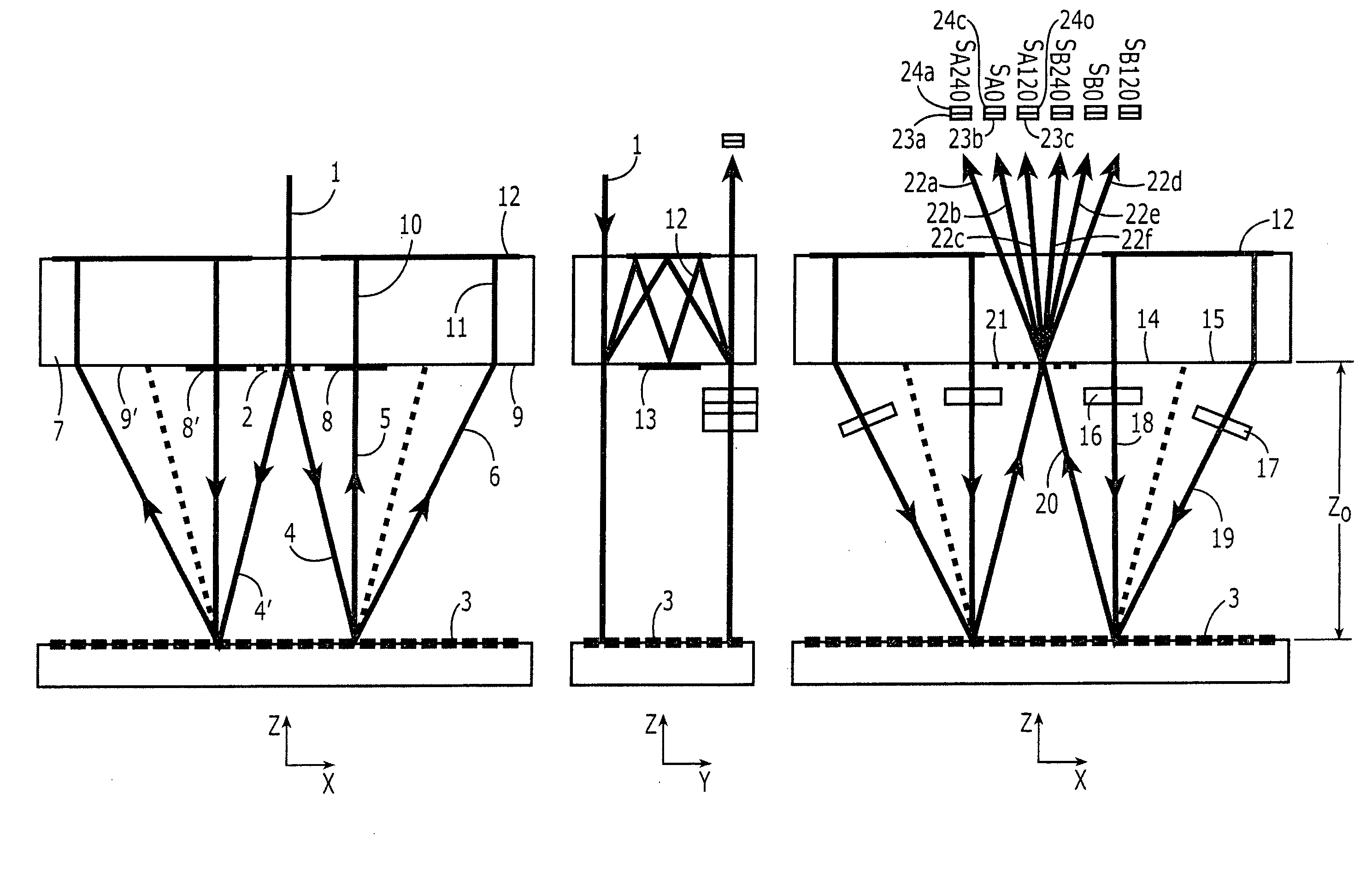
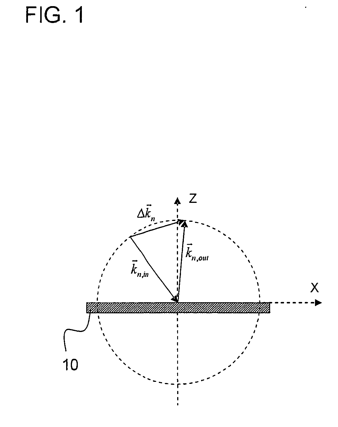
[0034] Before underlying principles of example embodiments of the present invention are discussed in further detail below, first a mathematical description of interferential position-measuring devices having measuring graduations in the form of gratings are explained. This is also used in the following to further describe example embodiments of the present invention.

[0035] In grating-based, interferential position-measuring devices, usually one beam of rays of a light source is split into two (or more) partial beams of rays. The partial beams of rays are shifted differently in their phase by diffraction at a material-measure grating, and ultimately brought to interference again. In this context, to the greatest extent possible, the traversed optical path lengths of both partial beams of rays should be of equal length. In this manner, the position values are made independent of the wavelength of the light source. Therefore, the beam paths of high-resolution position-measuring device...


PUM


Abstract

A position-measuring device is for measuring the position of two objects that are movable relative to one another. The device includes a measuring graduation, which is connected to one of the two objects, as well as at least one scanning system for scanning the measuring graduation, which is connected to the other of the two objects. The scanning system is arranged to permit a simultaneous determination of the position values along at least one lateral and along one vertical shift direction of the objects.

Description

CROSS-REFERENCE TO RELATED APPLICATIONS [0001] The present application claims priority to Application No. 10 2005 043 569.6, filed in the Federal Republic of Germany on Sep. 12, 2005, which is expressly incorporated herein in its entirety by reference thereto. FIELD OF THE INVENTION [0002] The present invention relates to an optical position-measuring device. BACKGROUND INFORMATION [0003] In semiconductor manufacturing devices, it is necessary to precisely determine the spatial position of certain parts, which are movable relative to each other, using suitable position-measuring devices. A computer-controlled sequencing control in these devices is then possible based on the position information. Thus, for example, in wafer steppers, the position of mask and wafer must be measured very precisely in all 6 degrees of freedom (6DOF). In conventional methods, this position measuring is mainly performed using several laser interferometers. In the future, it can be expected that the string...

Claims


Application Information

Patent Timeline
Patent Type & Authority Applications(United States)
IPC IPC(8): G01B11/02G01B9/02
CPCH05G2/008G01D5/38G01B9/02019G01B9/02022G01B9/02027G01B2290/30
Inventor HOLZAPFEL, WOLFGANG
Owner DR JOHANNES HEIDENHAIN GMBH
Why Eureka
Try Eureka