Capacitor microphone

a capacitor microphone and microphone body technology, applied in the field of capacitor microphones, can solve the problems of reducing the sensitivity of the capacitor microphone, the air gap (formed between the diaphragm electrode and the fixed electrode) becoming easily non-uniform, and the manufacturer experiences difficulty in manufacturing high-sensitivity capacitor microphones. , to achieve the effect of uniform distribution of stress, and improving design freedom

Inactive Publication Date: 2007-03-15
YAMAHA CORP
View PDF2 Cites 67 Cited by
  • Summary
  • Abstract
  • Description
  • Claims
  • Application Information

AI Technical Summary

Benefits of technology

[0027] As described above, the capacitor microphone realizes uniform distribution of stress applied to the circular plate of the diaphragm electrode because the stress absorbing portion of the extension terminal reliably absorbs the stress applied to the circular plate, thus realizing the uniform distribution of the stress applied to the circular plate. This produces the uniform gap between the fixed electrode and diaphragm electrode, thus improving the freedom of degree in designing. In addition, it is possible to improve the response because the circular plate smoothly vibrates without disturbances. This increases the bias voltage applied to the capacitor microphone, thus improving the sensitivity.

Problems solved by technology

That is, the other portions other than the center portion of the diaphragm having the uniform rigidity may reduce the sensitivity of the capacitor microphone.
In this case, a bias occurs when the diaphragm approaches the plate so as to cause electrostatic absorption, by which the plate absorbs the diaphragm; in other words, there is a problem regarding the occurrence of a pull-in event.
Due to such a restriction, the manufacturer experiences difficulty in manufacturing high-sensitivity capacitor microphones.
Even though the diaphragm electrode is supported in a hanging state and is separated from the insulating layer, a terminal for applying voltage from an external device is extended from a part of the outer circumferential portion of the diaphragm electrode and is fixed to the insulating layer, whereby the diaphragm electrode is supported in an unbalanced manner such that it is hung downwardly by means of the support and it is also supported horizontally by way of the terminal fixed to the insulating layer.
This makes the air gap (formed between the diaphragm electrode and the fixed electrode) become easily non-uniform, whereby the air gap may be reduced partially so as to cause a reduction of a pull-in potential.
Such a problem causes another limitation in increasing the bias voltage applied to the capacitor microphone.
Furthermore, the non-uniform air gap and the fixation of the terminal interfere with vibration of the diaphragm electrode, which may cause asymmetrical deformation with respect to the center of the diaphragm This produces dispersions of sensitivities and makes it difficult to predict the performance in designing.

Method used


Image

  • Capacitor microphone
  • Capacitor microphone
  • Capacitor microphone

Examples


first embodiment

1. First Embodiment

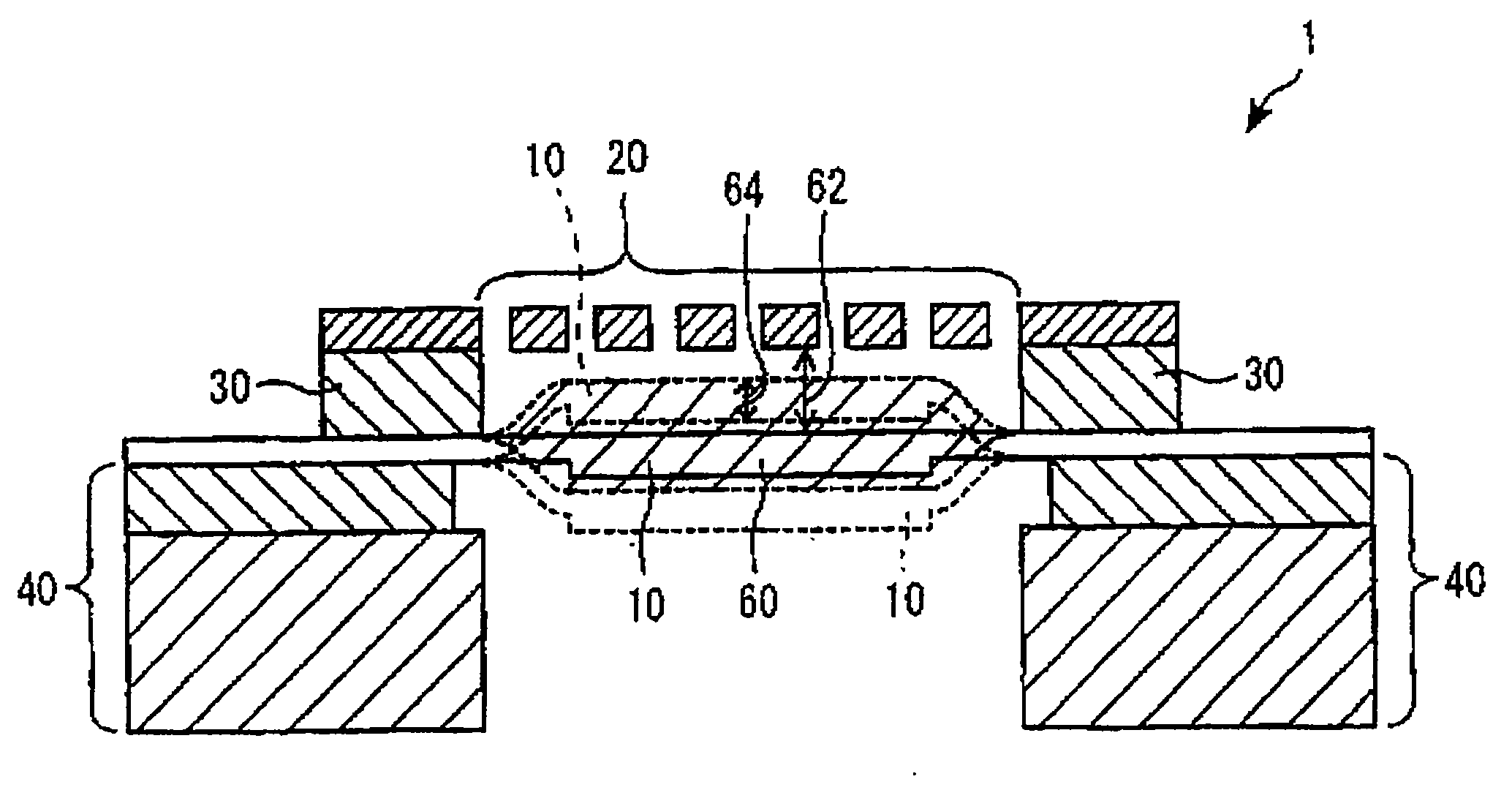
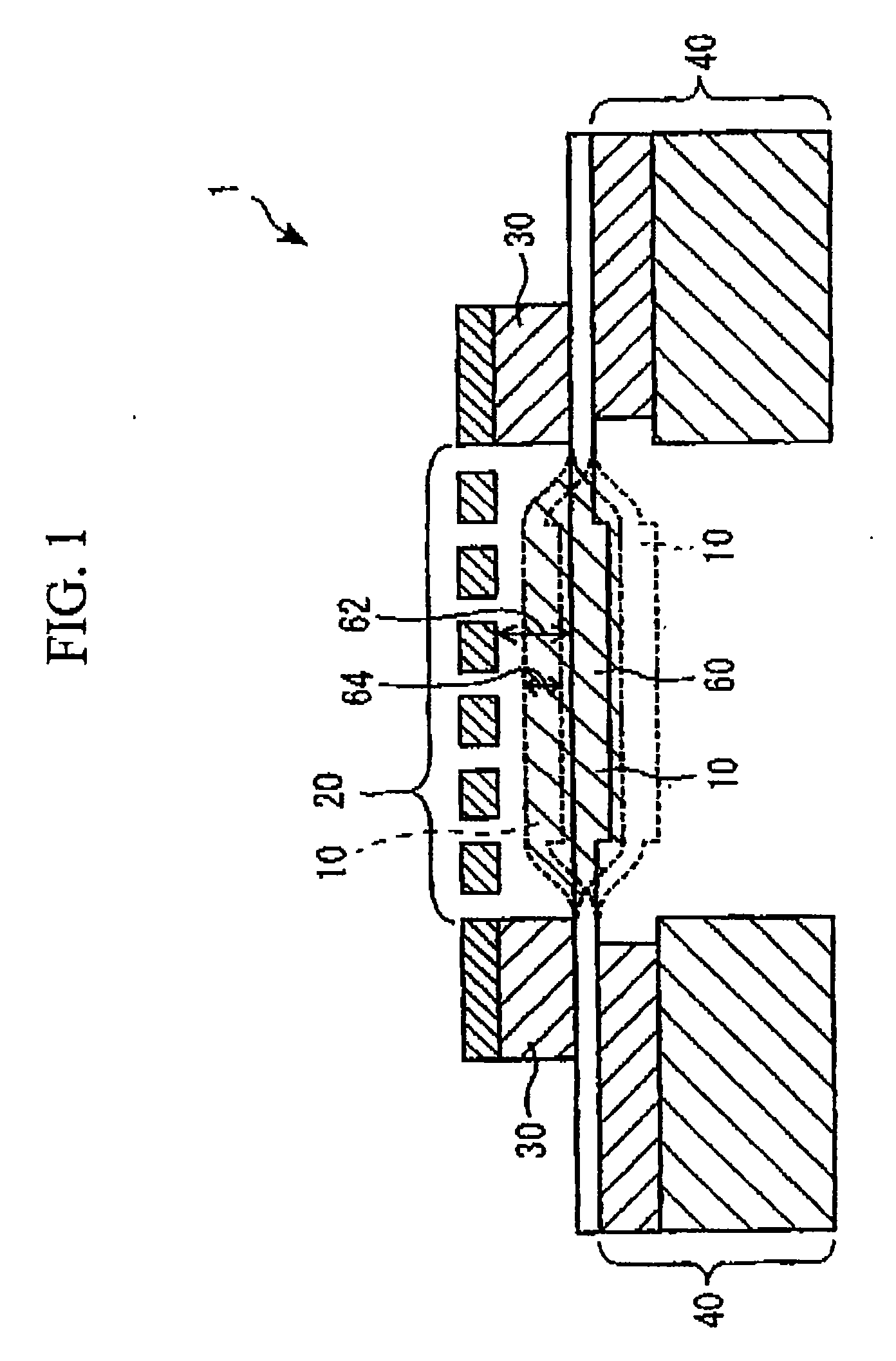
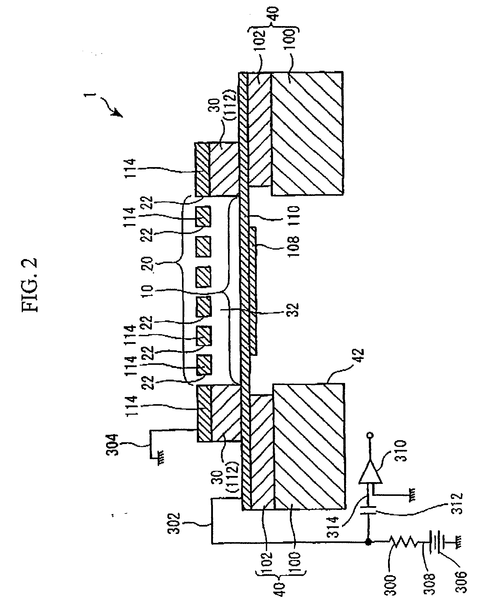
[0104] The overall constitution of a capacitor microphone according to a first embodiment of the present invention will be described with reference to FIG. 2 and FIGS. 3A and 3B. FIG. 2 is a cross-sectional view diagrammatically showing the constitution of a capacitor microphone 1; FIG. 3A is an upper view of a back plate 20 included in the capacitor microphone 1; and FIG. 3B is a lower view of a diaphragm 10 included in the capacitor microphone 1.

[0105] The capacitor microphone 1 is called a “silicon microphone” that is produced using semiconductor manufacturing processes. As shown in FIG. 2, the capacitor microphone 1 includes a sound sensing portion and a detection portion realized by electronic circuits.

(a) Constitution of Sound Sensing Portion

[0106] As shown in FIG. 2, the sound sensing portion of the capacitor microphone 1 is constituted by the aforementioned diaphragm 10 and the back plate 20 as well as a spacer 30 and a base 40.

[0107] The diaphragm 10...

second embodiment

2. Second Embodiment

[0133] Next, a capacitor microphone 2 according to a second embodiment of the present invention will be described with reference to FIGS. 7A and 7B. FIG. 7A is a cross-sectional view diagrammatically showing the constitution of the capacitor microphone 2, and FIG. 7B is a lower view diagrammatically showing a diaphragm 210 incorporated in the capacitor microphone 2. The capacitor microphone 2 has a detection portion, the constitution of which is substantially identical to the constitution of the detection portion of the capacitor microphone 1.

[0134] The diaphragm 210 is constituted by a conductive film 110 and a plurality of projections 200. The projections 200 are formed using a semiconductor film (or a second film) composed of polysilicon and are positioned in a radial manner about the center of the non-fixed portion of the conductive film 110 (or a first film). The density of the projections 200 is gradually increased in a direction from the outer periphery o...

third embodiment

3. Third Embodiment

[0145] Next, a capacitor microphone 3 according to a third embodiment of the present invention will be described with reference to FIGS. 11A and 11B. Herein, a center portion 14 of a diaphragm 11 has a two-layered structure including a conductive film 23 and a conductive film 110. The conductive film 110 functions as a reinforcement film, which increases the rigidity of the center portion 14 of the diaphragm 11 and is formed to entirely cover the center portion 14. A plurality of near-end portions 15 are formed in the diaphragm 11 by use of the conductive film 110, wherein they act as bridge structures for interconnecting the center portion 14 to the spacer 30. The near-end portions 15 are each bent and folded in a zigzag manner so as to function as springs, For this reason, the rigidity of the near-end portions 15 is extremely reduced in comparison with the rigidity of the center portion 14, so that the deformation of the diaphragm 11 transmitting sound waves mus...


PUM


Abstract

A capacitor microphone is constituted by a plate having a fixed electrode, a diaphragm including a center portion and at least one near-end portion that is fixed to the outer periphery, in which the center portion having a vibrating electrode, which is positioned relative to the fixed electrode and which vibrates in response to sound waves, is increased in rigidity in comparison with the near-end portion; and a spacer that is fixed to the plate and the near-end portion of the diaphragm and that has an air gap formed between the plate and the diaphragm. Alternatively, a diaphragm electrode is horizontally supported by extension arms extended from a circular plate thereof and is vertically held in a hanging state being apart from a fixed electrode with a controlled distance therebetween.

Description

TECHNICAL FIELD [0001] The present invention relates to capacitor microphones and in particular to capacitor microphones using semiconductor diaphragms. [0002] The present application claims priority on four Japanese patent applications, i.e., Patent Application No. 2005-261804 (filing date: Sep. 9, 2005), Patent Application No. 2006-167308 (filing date: Jun. 16, 2006), Patent Application No. 2006-188459 (filing date: Jul. 7, 2006), and Patent Application No. 2006-223425 (filing date: Aug. 18, 2006), the contents of which are incorporated herein by reference. BACKGROUND ART [0003] Conventionally, it is known that capacitor microphones can be manufactured in accordance with manufacturing processes used for semiconductor devices. Capacitor microphones are designed such that electrodes are attached to plates and diaphragms vibrating due to sound waves, wherein the plates and diaphragms are supported and distanced from each other by way of insulating spacers. Capacitor microphones conve...

Claims


Application Information

Patent Timeline
Patent Type & Authority Applications(United States)
IPC IPC(8): H04R25/00
CPCH04R19/04H04R19/005H04R7/02H04R19/016
Inventor SUZUKI, YUKITOSHISUZUKI, TAMITO
Owner YAMAHA CORP
Why Eureka
Try Eureka