Battery

a battery and a technology of a battery body, applied in the field of batteries, can solve the problems of short circuit between cathode and anode, lower stiffness of laminate films, etc., and achieve the effects of small force, reduced amount of active materials which can be filled in batteries, and reduced stiffness

Active Publication Date: 2007-03-15
MURATA MFG CO LTD
View PDF3 Cites 30 Cited by
  • Summary
  • Abstract
  • Description
  • Claims
  • Application Information

AI Technical Summary

Benefits of technology

[0007] However, a laminate film has lower stiffness than a package member made of metal such as aluminum or iron, so the laminate film has a small force to hold down a battery element in a battery. The battery element is a laminate including a cathode and an anode with a separator in between. Therefore, in a battery in which the package member is a laminate film, the application of external forces may cause relative displacement between the cathode, the anode and the separator in the battery element, thereby the cathode and the anode may be short-circuited. When the area of the separator is sufficiently larger than the area of an electrode, even if the relative displacement occurs, contact between the cathode and the anode can be prevented; however, in this case, an extra separator is included, so the amount of an active material which can be filled in the battery is reduced, thereby an energy density is reduced.

Problems solved by technology

However, a laminate film has lower stiffness than a package member made of metal such as aluminum or iron, so the laminate film has a small force to hold down a battery element in a battery.
Therefore, in a battery in which the package member is a laminate film, the application of external forces may cause relative displacement between the cathode, the anode and the separator in the battery element, thereby the cathode and the anode may be short-circuited.

Method used


Image

  • Battery
  • Battery
  • Battery

Examples


first embodiment

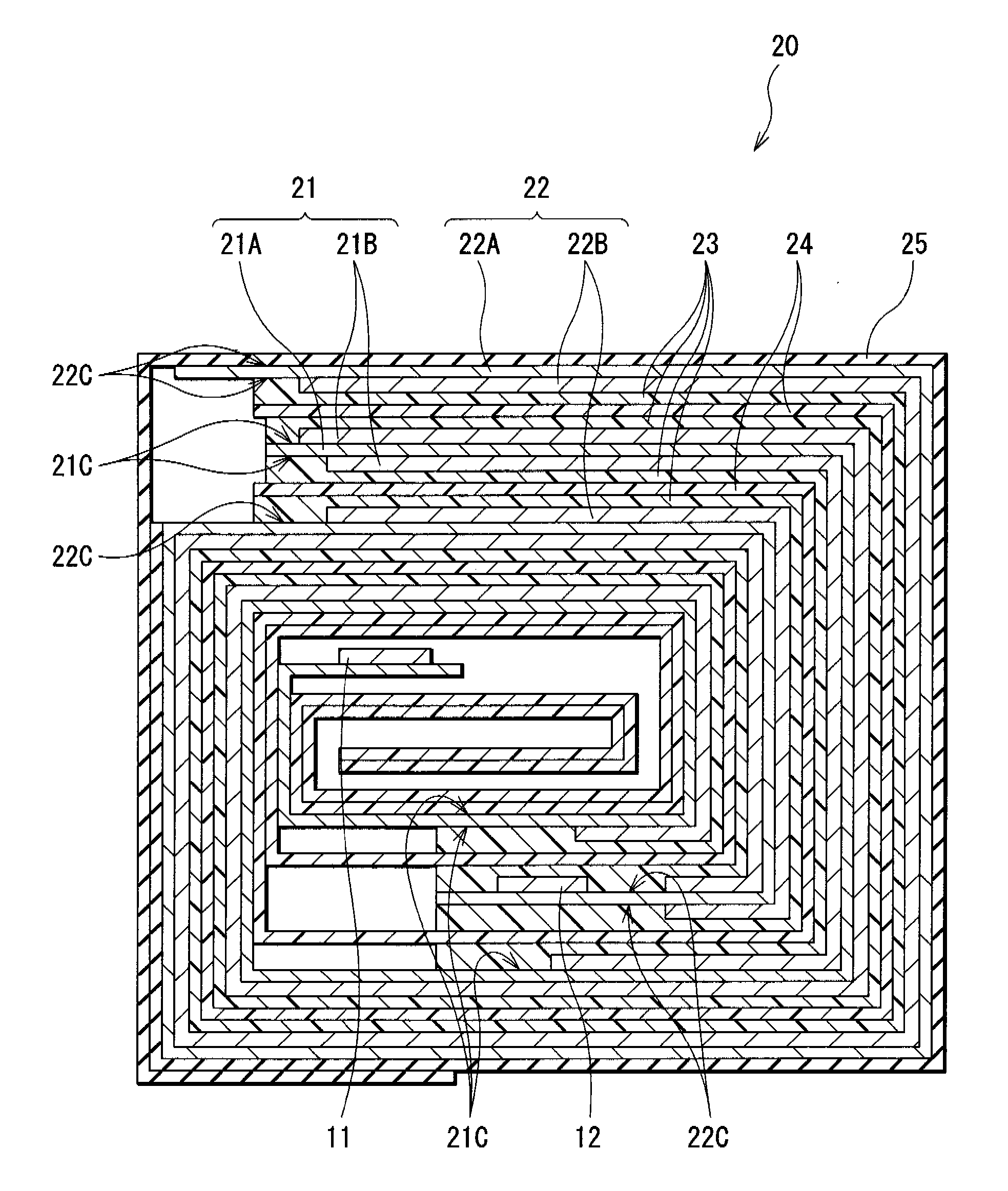
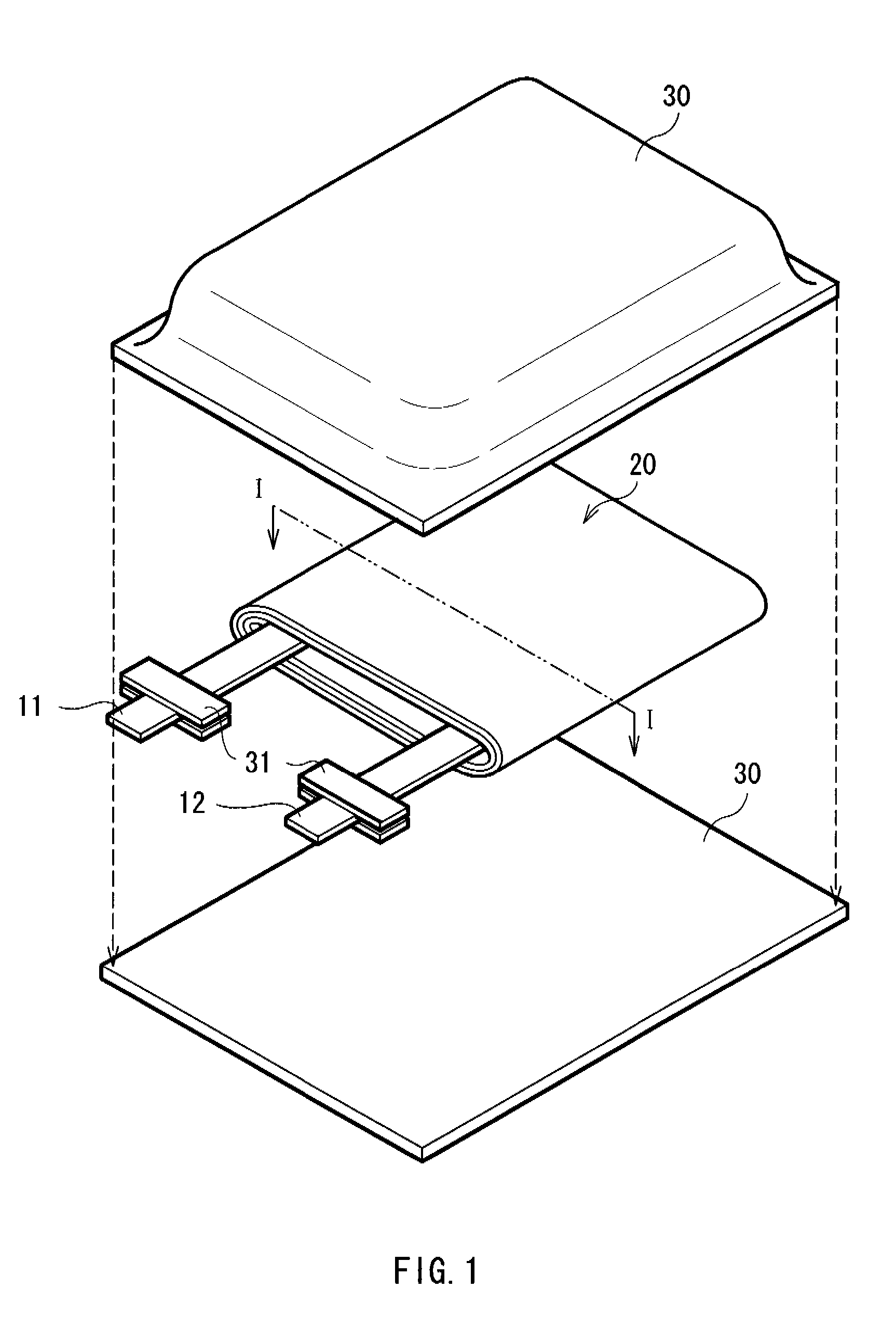
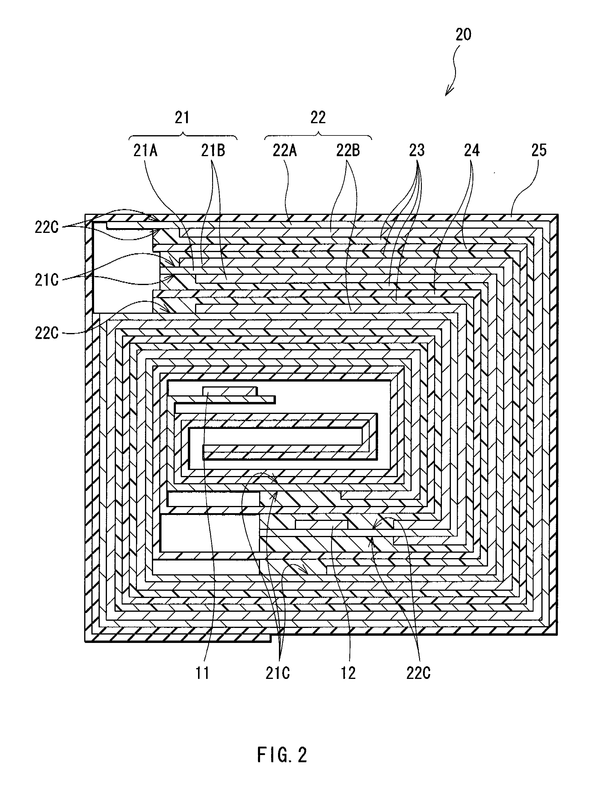
[0026]FIG. 1 shows the structure of a secondary battery 1 according to a first embodiment of the invention. The secondary battery 1 is specifically a winding type of so-called laminate film types, and in the secondary battery 1, a winding type battery element 20 to which a cathode terminal 11 and an anode terminal 12 are attached is contained in film-shaped package members 30.

[0027] The cathode terminal 11 and the anode terminal 12 are drawn from the interiors of the package members 30 to outside, for example, in the same direction. The cathode terminal 11 and the anode terminal 12 are made of, for example, a metal material such as aluminum, copper (Cu), nickel (Ni) or stainless in a sheet shape or a mesh shape.

[0028] The package members 30 are made of, for example, a rectangular aluminum laminate film including a nylon film, aluminum foil and a polyethylene film which are bonded in this order. The package members 30 are disposed so that the polyethylene film of each of the packag...

second embodiment

[0060]FIG. 4 shows the structure of a secondary battery 2 according to a second embodiment of the invention. The secondary battery 2 is specifically a laminate type of so-called laminate film types, and in the secondary battery 2, a laminate type battery element 50 to which a cathode terminal 41 and an anode terminal 42 are attached is contained in a film-shaped package members 61.

[0061] The cathode terminal 41 and the anode terminal 42 take out an electromotive force generated in the laminate type battery element 50 to outside, and each have a strap shape. They are drawn from the interiors of the package members 61 to outside, for example, in the same direction. The cathode terminal 41 and the anode terminal 42 have the same structures as the cathode terminal 11 and the anode terminal 12 in the secondary battery 1 shown in FIG. 1, respectively. An adhesive film 61 is inserted between the package members 61 and the cathode terminal 41 and the anode terminal 42 for preventing the en...

examples

[0080] Specific examples of the invention will be described in detail below.


PUM

PropertyMeasurementUnit
peel strengthaaaaaaaaaa
thicknessaaaaaaaaaa
short-circuit aaaaaaaaaa

Abstract

A battery in which the relative positions of a cathode, an anode and a separator are maintained with high precision is provided. A cathode and an anode face each other with a polymer electrolyte including a polymer and a separator in between. In each of the cathode and the anode, an active material layer is disposed on a current collector. Exposed regions where the active material layers are not disposed on the current collectors and the separator are adhered to each other with the polymer electrolyte in between. Thereby, even under a high-temperature environment, the heat shrinkage of the separator can be prevented, and heat generation due to the generation of a short-circuit current can be prevented.

Description

CROSS REFERENCES TO RELATED APPLICATIONS [0001] The present invention contains subject matter related to Japanese Patent Application JP 2005-262494 filed in the Japanese Patent Office on Sep. 9, 2005, and Japanese Patent Application JP 2006-149242 filed in the Japanese Patent Office on May 30, 2006, the entire contents of which being incorporated herein by references. BACKGROUND OF THE INVENTION [0002] 1. Field of the Invention [0003] The present invention relates to a battery using a polymer electrolyte including a polymer. [0004] 2. Description of the Related Art [0005] In recent years, a large number of portable electronic devices such as camcorders, cellular phones and portable computers have emerged, and an attempt to reduce the size and the weight of them has been made. Accordingly, the development of batteries as portable power sources of the electronic devices, specifically secondary batteries have been actively promoted. Among the batteries, a lithium-ion secondary battery ...

Claims


Application Information

Patent Timeline
Patent Type & Authority Applications(United States)
IPC IPC(8): H01M2/16H01M2/08H01M10/05H01M10/0565H01M10/058H01M10/0585H01M10/0587H01M50/409H01M50/489
CPCH01M2/16H01M4/66H01M2300/0082H01M10/0436H01M10/0565H01M6/10H01M50/409H01M50/489Y02E60/10Y02P70/50
Inventor NAKAMURA, TOMOYUKIENDO, TAKAHIROAKASHI, HIROYUKI
Owner MURATA MFG CO LTD
Why Eureka
Try Eureka