
Multi-featured arrays with reflective coating

a reflective coating and array technology, applied in the field of optical illumination and optical sensing of arrays, can solve the problems of low dna availability, low dna quality, and low cost of arrays, and achieve the effect of reducing source output power, maximizing signal which can be detected, and maintaining detected nois

Inactive Publication Date: 2007-03-15
DORSEL ANDREAS N +2
View PDF57 Cites 0 Cited by
  • Summary
  • Abstract
  • Description
  • Claims
  • Application Information

AI Technical Summary

Benefits of technology

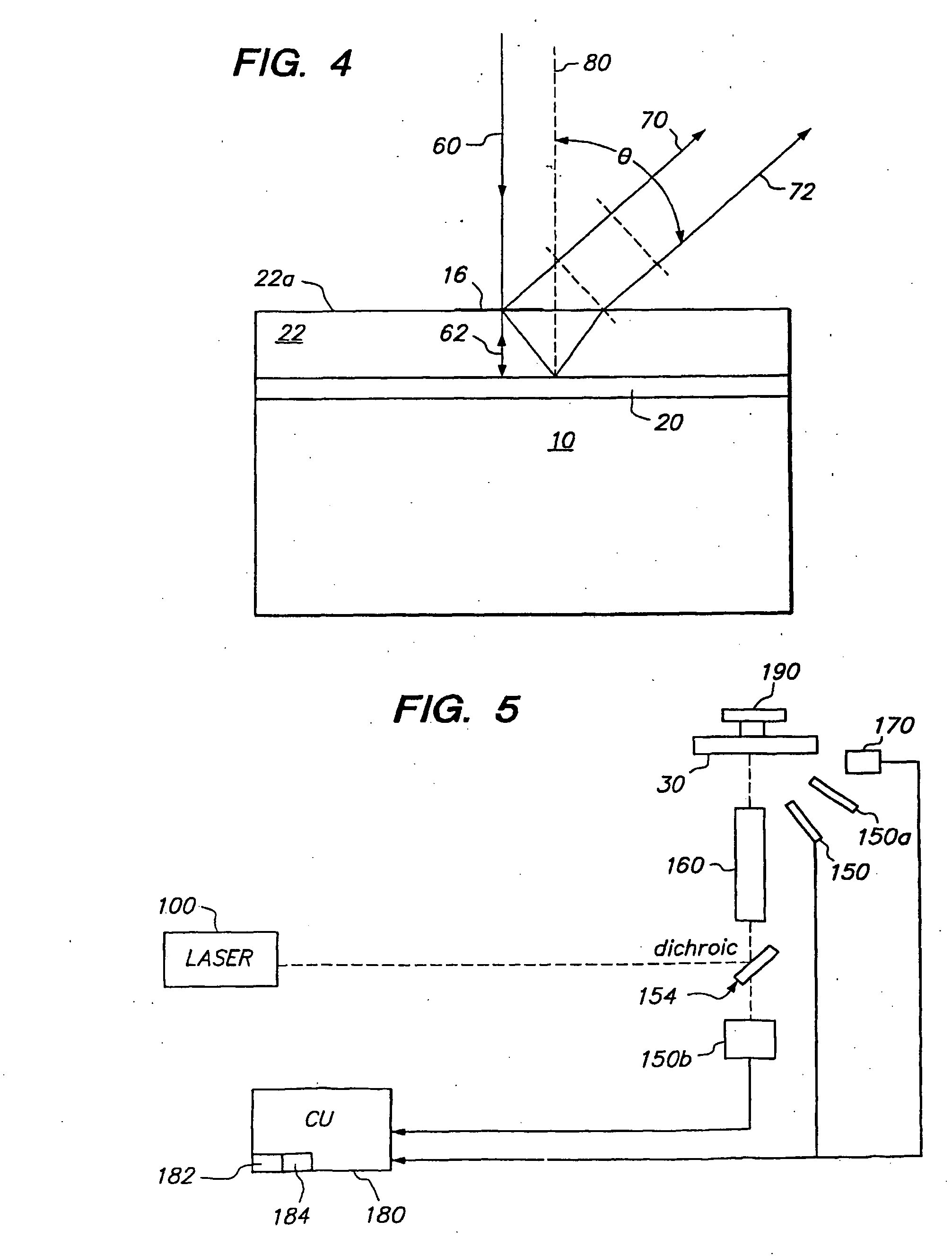
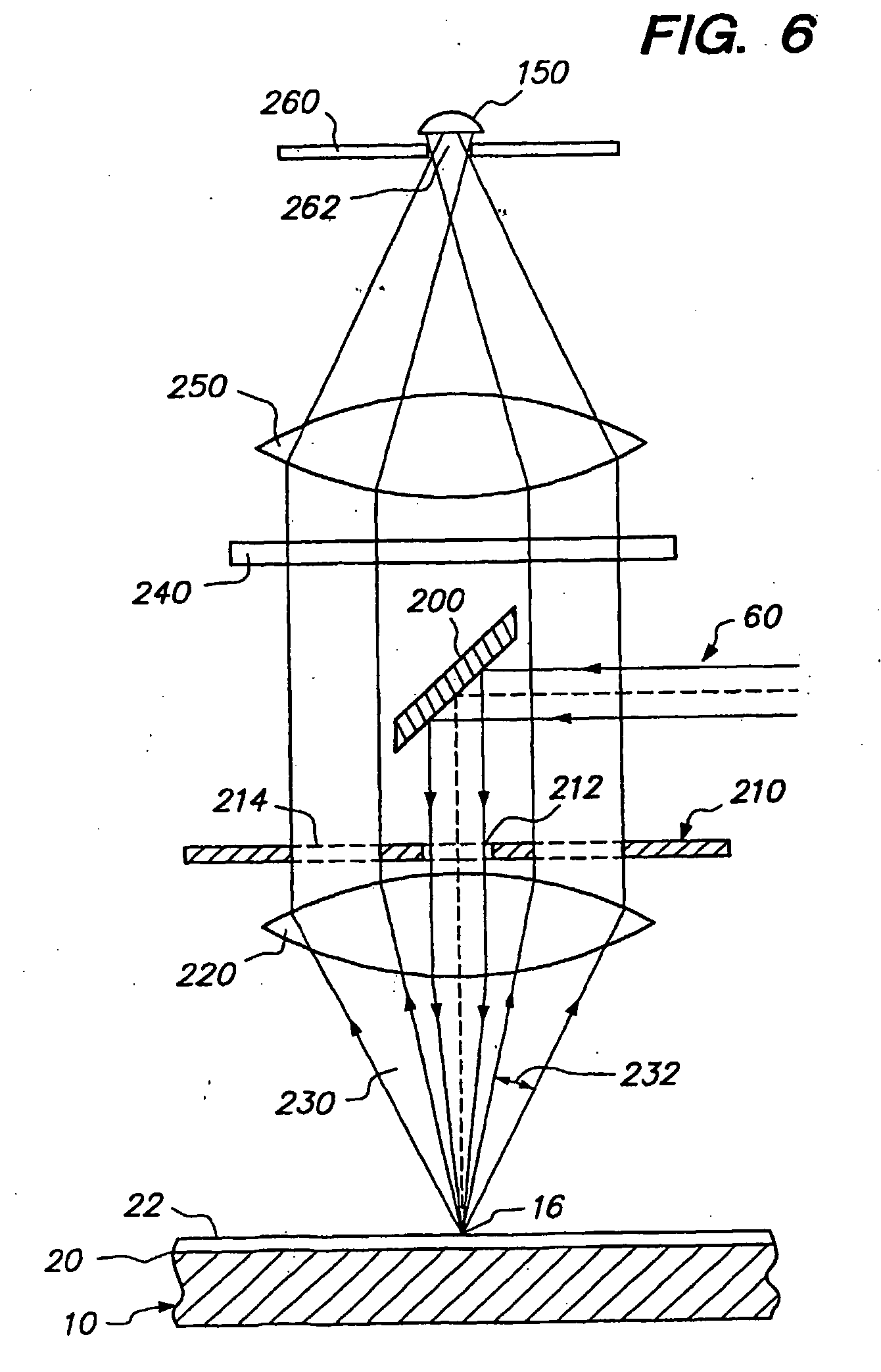
[0018] The present invention then can provide any one or more of a number of advantages. For example, a higher interrogation light power can be provided at a feature without having to increase the output available from the interrogating light source, or the same interrogating light power can be obtained at the feature and the source output power lowered. Also, high detected signal can be obtained without having to further increase interrogating light power (and possibly risking saturation in certain situations), while maintaining detected noise at a low level. Combinations of the foregoing are also possible. By adjusting spacer layer thickness and detection angle for a given array the signal which can be detected can be maximized. By providing a reflecting layer, the detector also does not receive light emitted from the substrate, reducing the need for confocal detection and an auto-focus detector system while still providing high depth discrimination. Also, with constructive interference of reflected and non-reflected emitted light, such emitted light can be concentrated on or near the surface of a cone positioned with an apex at the features. This can simplify the ability to capture more of the emitted light.

Problems solved by technology

In array fabrication, the quantities of DNA available for the array are usually very small and expensive.
However, this also results in capture of only a very small proportion of the emitted fluorescent light.
While detectors may be highly sensitive, the fluorescence detected may still be very weak, particularly where very little of a fluorescently labeled target is bound to a particular array feature.
Weak signals may lead to errors in array interrogation and subsequent misinterpretation of results.
Furthermore, increasing interrogating light power to a feature is not always an option, since fluorescent moieties rapidly become saturated such that an increase in interrogating light power does not increase signal, but may increase noise.

Method used


Image

  • Multi-featured arrays with reflective coating
  • Multi-featured arrays with reflective coating
  • Multi-featured arrays with reflective coating

Examples


Embodiment Construction

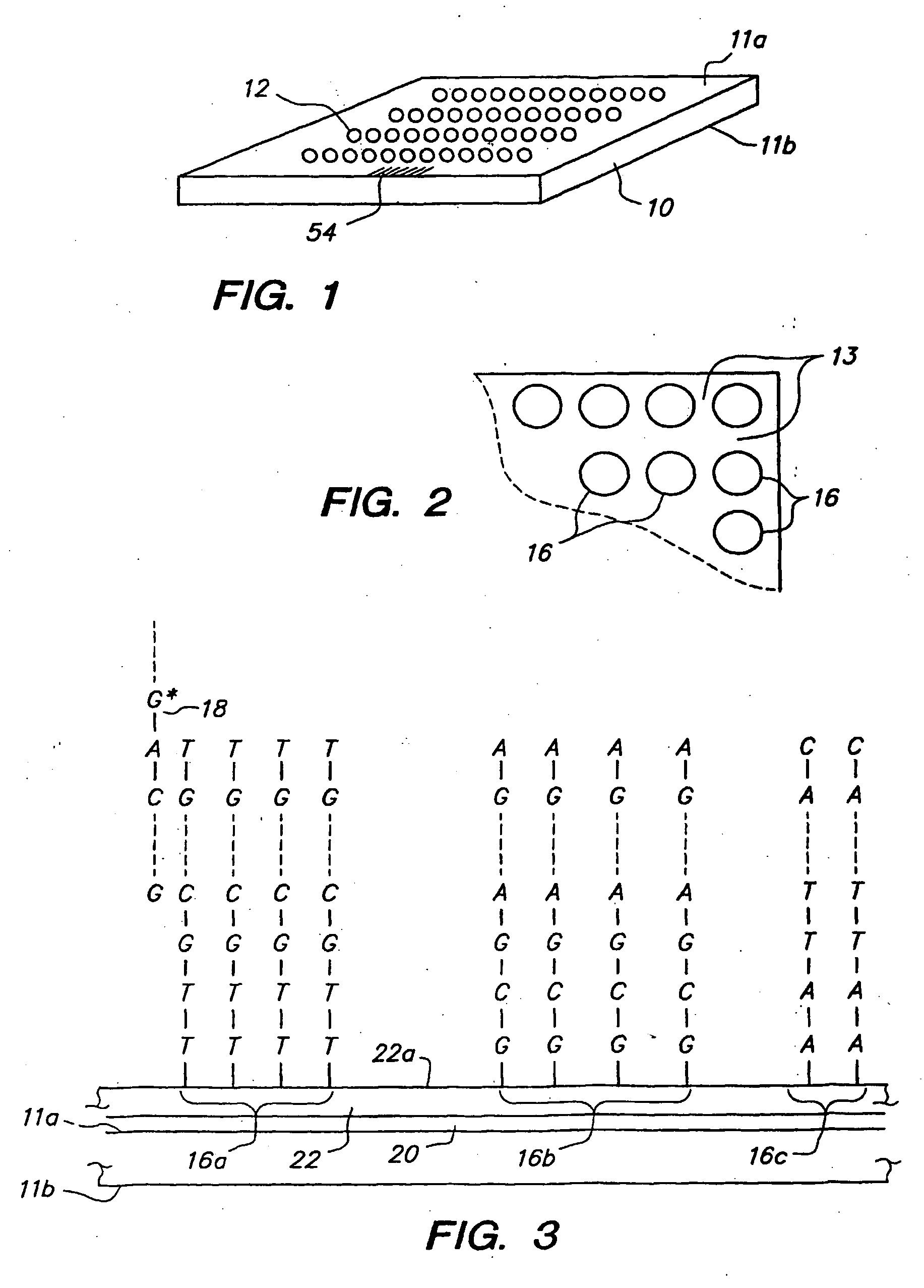
[0028] Throughout the present application, unless a contrary intention appears, the following terms refer to the indicated characteristics. A “biopolymer” is a polymer of one or more types of repeating units. Biopolymers are typically found in biological systems and particularly include peptides or polynucleotides, as well as such compounds composed of or containing amino acid or nucleotide analogs or non-nucleotide groups. This includes polynucleotides in which the conventional backbone has been replaced with a non-naturally occurring or synthetic backbone, and nucleic acids (or synthetic or naturally occurring analogs) in which one or more of the conventional bases has been replaced with a group (natural or synthetic) capable of participating in Watson-Crick type hydrogen bonding interactions. Polynucleotides include single or multiple stranded configurations, where one or more of the strands may or may not be completely aligned with another. A “nucleotide” refers to a sub-unit of...


PUM

PropertyMeasurementUnit
detection angleaaaaaaaaaa
thickaaaaaaaaaa
thickaaaaaaaaaa

Abstract

A method and apparatus of interrogating an addressable array unit, which includes a substrate, a light reflecting layer on a front side of the substrate, and a plurality of features on a front side of the array. The method may include, for each of multiple features, illuminating the feature simultaneously with reflected and non-reflected interrogating light. A light emitted from respective features is detected. Either or both, constructive interference of interrogating light at the features, or constructive interference of light emitted from the features, can be obtained to allow lowering of light power from the source, enhanced signal, or reduced noise, or combinations of the foregoing. High depth discrimination may also be obtained without the need for a confocal detection system with conventional pinhole.

Description

FIELD OF THE INVENTION [0001] This invention relates to optical illumination and optical sensing of arrays, particularly biopolymer arrays such as DNA arrays, which are useful in diagnostic, screening, gene expression analysis, and other applications. BACKGROUND OF THE INVENTION [0002] Polynucleotide arrays (such as DNA or RNA arrays), are known and are used, for example, as diagnostic or screening tools. Such arrays include features (sometimes referenced as spots or regions) of usually different sequence polynucleotides arranged in a predetermined configuration on a substrate. The array is “addressable” in that different features have different predetermined locations (“addresses”) on a substrate carrying the array. [0003] Biopolymer arrays can be fabricated using in situ synthesis methods or deposition of the previously obtained biopolymers. The in situ synthesis methods include those described in U.S. Pat. No. 5,449,754 for synthesizing peptide arrays, as well as WO 98 / 41531 and ...

Claims


Application Information

Patent Timeline
Patent Type & Authority Applications(United States)
IPC IPC(8): C12Q1/68C12M1/34
CPCG01N21/6452G01N21/6428
Inventor DORSEL, ANDREAS N.KING, DAVID A.SAMPAS, NICHOLAS M.
Owner DORSEL ANDREAS N
Learn More