Method of producing a mixture of ozone and high pressure carbon dioxide

a technology of ozone and carbon dioxide, which is applied in the direction of hydrogen peroxide, bulk chemical production, separation processes, etc., can solve the problems of inability to remove incomplete resisting, unwanted debris with dimensions comparable to device dimensions, and inability to meet the requirements of the application

Inactive Publication Date: 2007-03-22
BOC GRP INC
View PDF19 Cites 13 Cited by
  • Summary
  • Abstract
  • Description
  • Claims
  • Application Information

AI Technical Summary

Benefits of technology

[0011] One embodiment of the present invention relates to an apparatus comprising an adsorption bed, an oxidizer source connected to the adsorption bed wherein the oxidizer is at a first pressure, a high pressure fluid source connected to the adsorption bed wherein the high pressure fluid is at a second pressure, the second pressure being greater than the first pressure, a depleted oxidizer outlet, and a fluid mixture outlet comprising a mixture of oxidizer and high pressure fluid.
[0012] According to another embodiment of the present invention, the apparatus includes a first and a second adsorption bed, an oxidizer source connected to the adsorption beds wherein the oxidizer is at a first pressure, a high pressure fluid source connected to the adsorption beds wherein the high pressure fluid is at a second pressure, the second pressure being greater than the first pressure, a depleted oxidizer outlet connected to the adsorption beds, and a fluid outlet comprising a mixture of oxidizer and high pressure fluid.
[0013] One method according to the present invention comprises adsorbing an oxidizer in an adsorption bed, desorbing the oxidizer by adsorbing a high pressure fluid in the adsorption bed, producing an outlet fluid mixture of oxidizer and high pressure fluid, and directing the outlet fluid mixture to a device.

Problems solved by technology

Although adequate for many purposes, these techniques have been found to possess drawbacks now that device dimensions are in the submicron regime.
First, there may be unwanted debris remaining with dimensions comparable to device dimensions.
Second, resist removal may be incomplete.
It has been found that some process steps, for example, dry etching, may harden a portion of the resist and render it impervious to conventional stripping techniques.
While it is desirable to mix ozone from an ozone generator, the ozone being at a low pressure, with a fluid such as SCCO2, which is at high pressure, such mixing of fluids at different pressures is generally difficult and additional apparatus and methods for forming a mixture of SCCO2 and ozone are desirable.

Method used


Image

  • Method of producing a mixture of ozone and high pressure carbon dioxide
  • Method of producing a mixture of ozone and high pressure carbon dioxide
  • Method of producing a mixture of ozone and high pressure carbon dioxide

Examples


Embodiment Construction

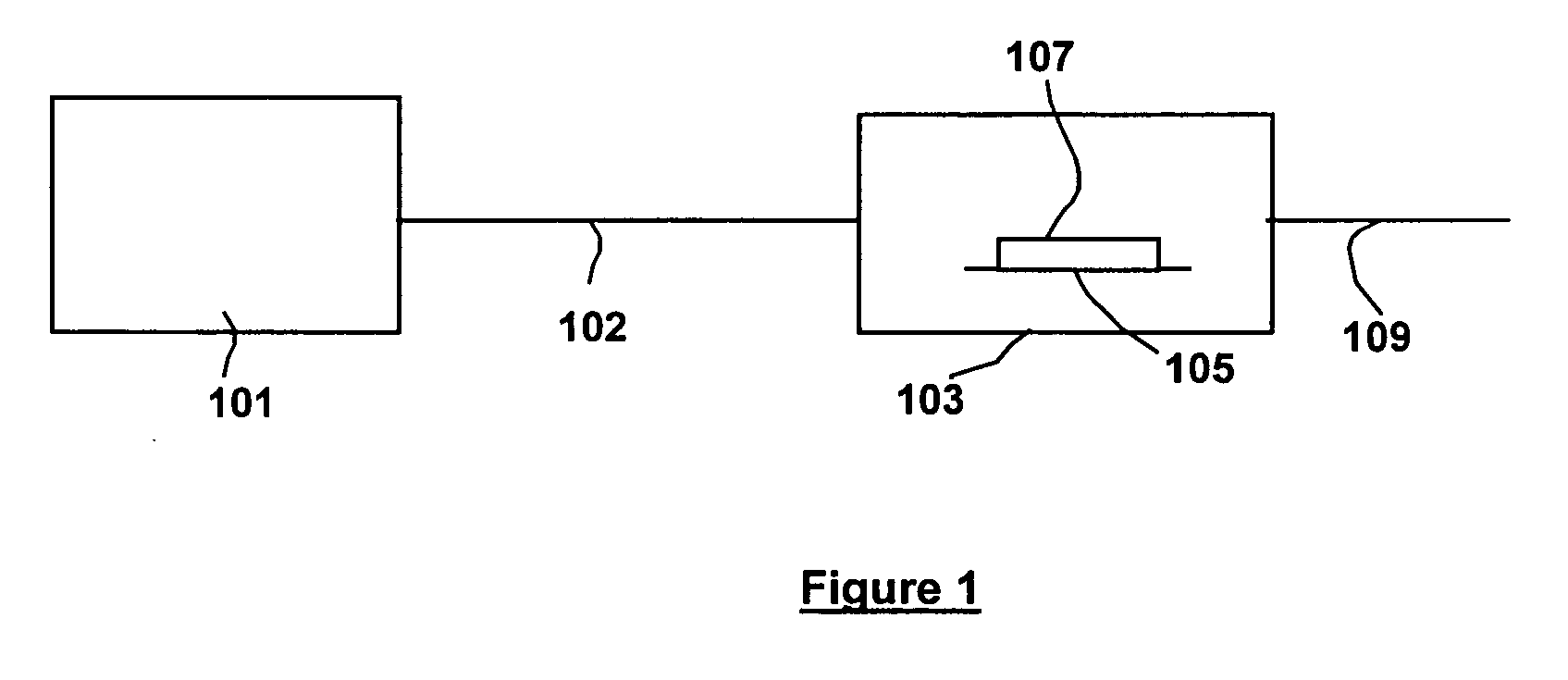
[0017]FIG. 1 is a schematic representation of one embodiment of an apparatus according to the present invention for producing a mixture of oxidizer and high pressure fluid in a batch system. Depicted are fluid mixture source 101, cleaning chamber 103, and fluid outlet 109. Line 102 connects fluid mixture source 101 and cleaning chamber 103. “Line” is used to mean a pipe or other structure capable of conveying fluids. In a typical embodiment for cleaning of semiconductor wafers, cleaning chamber 103 is a single wafer post etch chamber. Within cleaning chamber 103 are substrate support 105 which supports the wafer 107 that is to be cleaned. Standard elements of the apparatus are not depicted for reasons of clarity. For example, fluid outlet 109 may go to a recycle apparatus that removes solvents and debris from the fluid and then recycles the fluid to fluid mixture source 101. Further, the cleaning chamber 103, fluid outlet 109 and line 102 represent standard components known in the i...


PUM

PropertyMeasurementUnit
pressureaaaaaaaaaa
pressureaaaaaaaaaa
pressureaaaaaaaaaa

Abstract

Mixtures of an oxidizer and a high pressure fluid are produced by adsorbing an oxidizer in an adsorption bed and then desorbing the oxidizer with a high pressure fluid. The same steps can simultaneously occur in a second adsorbing bed but in reverse order. The oxidizer may be ozone and the high pressure fluid may be high pressure C02 including supercritical C02. Such mixtures can be used for applications such as cleaning semiconductor wafers, food disinfection and water disinfection.

Description

TECHNICAL FIELD [0001] This invention relates generally to method and apparatus for producing a mixture of an oxidizer and a high pressure fluid useful for cleaning objects such as integrated circuit wafers and for disinfecting food or water and particularly to method and apparatus for producing a mixture of ozone and supercritical or high pressure carbon dioxide (SCCO2 or HPCO2) useful for cleaning objects and for disinfecting food or water. BACKGROUND OF THE INVENTION [0002] Cleaning objects prior to performing work on them is an essential step in many manufacturing processes. One manufacturing process will be discussed in detail. For example, semiconductor integrated circuit manufacture has many steps in which a pattern is transferred from a mask to a substrate. The pattern is typically transferred by selective exposure of the substrate to radiation through a mask. The substrate is coated with a radiation sensitive material, termed a resist, whose solubility when exposed to an a...

Claims


Application Information

Patent Timeline
Patent Type & Authority Applications(United States)
IPC IPC(8): B01D53/02
CPCB01D53/0454B01D53/047B01D2251/104B01D2253/106B01D2256/14C01B31/20B01D2259/40086B01D2259/402C01B13/10C01B15/01C01B21/0837B01D2256/22C01B32/50Y02P20/54
Inventor JAIN, RAVI
Owner BOC GRP INC
Why Eureka
Try Eureka